Forward-flyback switching power supply circuit and control method thereof

A switching power supply circuit, flyback technology, applied in the direction of control/regulation systems, high-efficiency power electronic conversion, electrical components, etc., can solve the problems of large volume, complex transformer design, etc., to reduce current changes, improve efficiency, reduce The effect of the output ripple

Active Publication Date: 2020-11-03
MORNSUN GUANGZHOU SCI & TECH
View PDF3 Cites 1 Cited by
  • Summary
  • Abstract
  • Description
  • Claims
  • Application Information

AI Technical Summary

Problems solved by technology

The design of the transformer used in the wide input range of the forward and flyback converter is more complex and larger, and the output ripple of the converter is affected by the current of the forward loop

Method used


Image

  • Forward-flyback switching power supply circuit and control method thereof
  • Forward-flyback switching power supply circuit and control method thereof
  • Forward-flyback switching power supply circuit and control method thereof

Examples


no. 1 example

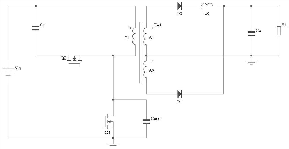
[0033] figure 1 It is the circuit schematic diagram of the primary-side clamp forward-flyback converter of the first embodiment of the present invention, a forward-flyback switching power supply circuit, including a primary-side winding unit, an active clamping circuit and a secondary-side winding unit; the primary-side winding The unit includes the DC source Vin, the primary winding P1 of the transformer TX1, the main switch tube Q1 and the active clamp circuit; the active clamp circuit is a buck-boost active clamp circuit, including the auxiliary switch tube Q2 and the clamp capacitor Cr The secondary winding unit includes transformer TX1 secondary winding S1 (also called forward winding), transformer TX1 secondary winding S2 (also called flyback winding), rectifier diode D1, rectifier diode D3, output inductor Lo, Output capacitor Co and load RL.

[0034] The connection relationship of the forward and flyback switching power supply circuit of the first embodiment of the pr...

no. 2 example

[0051] figure 2 It is the circuit principle diagram of the forward-flyback switching power supply circuit of the second embodiment of the present invention, which is different from the first embodiment in that a boost-type active clamping circuit is adopted. Boost-type active clamping circuit, connected in parallel at both ends of the main switch tube Q1, including the auxiliary switch tube Q2 and capacitor Cr, where one end of the capacitor Cr is connected to the drain of the main switch tube Q1 and the primary winding of the transformer TX1 respectively The opposite terminal of P1 is connected, the other end of the capacitor Cr is connected to the source of the auxiliary switch Q2, and the drain of the auxiliary switch Q2 is connected to the source of the main switch Q1 and the negative terminal of the DC source Vin.

no. 3 example

[0053] image 3 It is the circuit principle diagram of the forward-flyback switching power supply circuit of the third embodiment of the present invention, which is different from the first embodiment in that a step-down active clamping circuit is applied. Step-down active clamping circuit, including auxiliary switch tube Q2 and capacitor Cr, wherein the drain of the auxiliary switch tube Q2 is connected to the positive terminal of the DC source Vin and one end of the capacitor Cr, and the other end of the capacitor Cr is connected to the transformer The terminal with the same name of the primary winding P1 of TX1 is connected, and the source of the auxiliary switching tube Q2 is connected with the terminal of the same name of the primary winding P1 of the transformer TX1.


PUM


Abstract

The invention provides a forward-flyback power supply circuit, and the circuit integrates the advantages of a forward converter and a flyback converter and utilizes the characteristic that an output inductor changes along with the change of an input voltage to reduce the change rate of the current of a forward loop at a high-low voltage current. In addition, by adjusting the number of turns of theforward winding and the inductance value of the output inductor, it can be guaranteed that the current of the forward loop is basically kept unchanged at high voltage and low voltage, and therefore the size of the forward-reverse converter is reduced, and output ripples are reduced through reasonable energy distribution of the forward loop and the flyback loop; the ZVS of the main switching tubeis realized by utilizing the active clamping circuit, so the efficiency of the flyback converter is improved, and the EMI is improved.

Description

technical field [0001] The invention relates to a switching power supply circuit, in particular to a forward and flyback switching power supply circuit. Background technique [0002] The forward and flyback converter combines the advantages of the forward converter and the flyback converter, and has relatively good overall performance. The forward and flyback converter uses a transformer to realize the functions of the forward transformer and the flyback transformer, making the use of the transformer more efficient. full. The output current of the forward and flyback transformer is provided by both the flyback loop and the forward loop. Ideally, the proportion of the total current of the forward loop in the forward and flyback converter remains unchanged at high voltage and low input, so that the forward and flyback converter Maximize utilization and minimize volume. In the current existing technology, the current of the forward circuit will increase with the increase of t...

Claims


Application Information

Patent Timeline
Patent Type & Authority Applications(China)
IPC IPC(8): H02M3/335H02M1/14
CPCH02M3/33523H02M1/14Y02B70/10
Inventor 尹向阳钟辉王志燊
Owner MORNSUN GUANGZHOU SCI & TECH
Why Eureka
Try Eureka