Eureka AIR delivers breakthrough ideas for toughest innovation challenges, trusted by R&D personnel around the world.

Heat-dissipating bracket forming die for main board of industrial camera

A heat dissipation bracket and industrial camera technology, applied in the field of industrial camera production, can solve problems such as deformation and damage of ribs 110, difficult demoulding, etc., and achieve the effect of avoiding deformation and damage of ribs

Pending Publication Date: 2020-11-06
嘉兴合祖机电设备有限公司
View PDF0 Cites 0 Cited by
  • Summary
  • Abstract
  • Description
  • Claims
  • Application Information

AI Technical Summary

Problems solved by technology

Existing molds are only provided with some thimbles in the lower mold, and the thimbles hold up the newly formed industrial camera main board heat dissipation bracket 100 when demolding, but due to the existence of several convex ribs 110, the industrial camera main board heat dissipation support 100 is Adhesion occurs between ribs 110 and the upper mold, making it difficult to demould smoothly, or the ribs 110 are deformed and damaged during demoulding

Method used


Image

  • Heat-dissipating bracket forming die for main board of industrial camera
  • Heat-dissipating bracket forming die for main board of industrial camera
  • Heat-dissipating bracket forming die for main board of industrial camera

Examples


Embodiment Construction

[0021] Specific embodiments of the present invention will be described in further detail below based on the accompanying drawings. It should be understood that the description of the embodiments of the present invention here is not intended to limit the protection scope of the present invention.

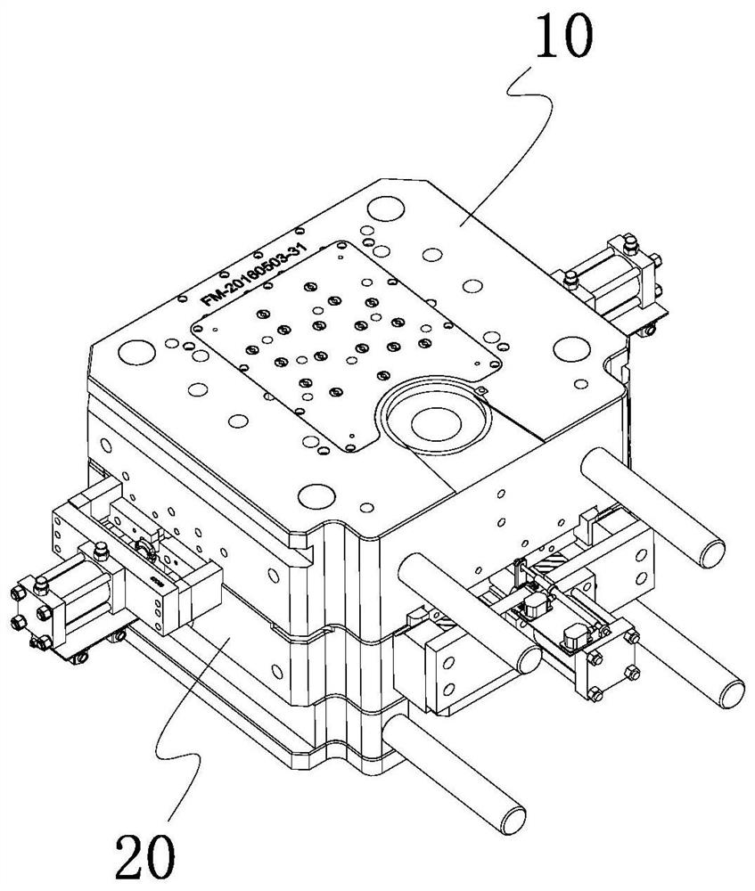
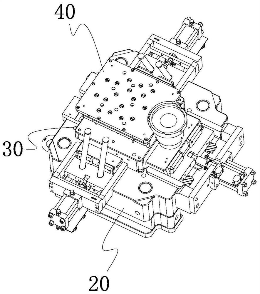
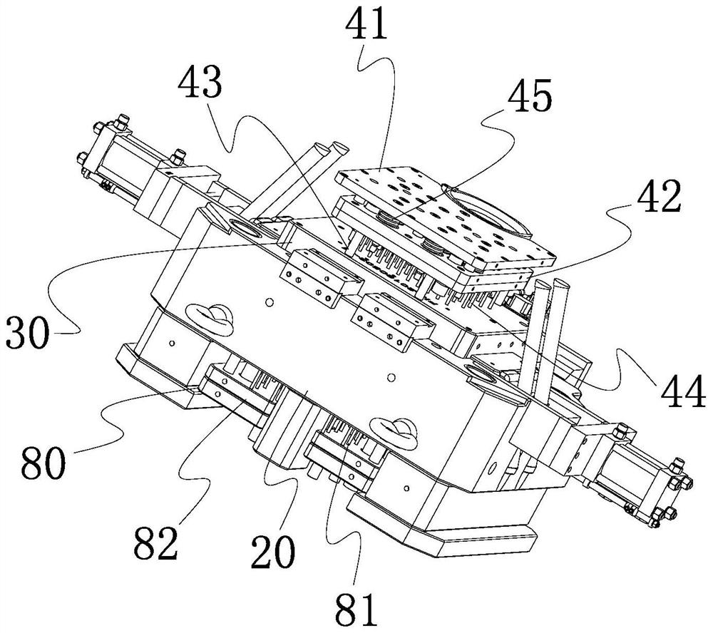
[0022] Please refer to Figure 1 to Figure 6 , The industrial camera mainboard heat dissipation bracket forming mold provided by the present invention includes an upper mold base 10, a lower mold base 20, an upper mold 30, an upper mold demoulding assembly 40, a lower mold 50 and a lower mold demoulding assembly 80.

[0023] The upper mold base 10 is arranged opposite to the lower mold base 20 , the upper mold base 30 is arranged on the bottom surface of the upper mold base 10 towards the lower mold base 20 , and the lower mold 50 is arranged on the upper surface of the lower mold base 20 towards the upper mold base 10 .

[0024] The upper mold release assembly 40 includes an upper ...


PUM


Abstract

The invention relates to a heat-dissipating bracket forming die for a main board of an industrial camera. The die comprises an upper die seat, a lower die seat, an upper die, an upper die stripping assembly, a lower die and a lower die stripping assembly, wherein the upper die stripping assembly comprises an upper stripping fixing plate, an upper stripping moving plate, a plurality of connecting columns, a plurality of upper striping ejector pins and a plurality of springs. The upper stripping fixing plate is arranged on the side, far away from the lower die, of the upper die and is connectedto the upper die seat; the upper stripping moving plate is movably located between the upper stripping fixing plate and the upper die, and the springs are located between the upper stripping moving plate and the upper stripping fixing plate; the first ends of the connecting columns are connected to the part, close to the edge, of the upper stripping moving plate, and the second ends of the connecting columns lean against the part, close to the edge, of the upper die; the first ends of the upper stripping ejector pins are fixedly connected to the upper striping moving plate, a plurality of upper ejector pin holes are formed in the upper die, and the second ends of the upper stripping ejector pins penetrate the upper ejector pin holes of the upper die. Therefore, stripping of a product and an upper die bracket can be achieved automatically, and deformation and damage of a convex rib of the product can be avoided.

Description

technical field [0001] The invention relates to the technical field of industrial camera production, in particular to a mold for forming a cooling bracket for an industrial camera motherboard. Background technique [0002] Please refer to Figure 7 The back side of the industrial camera motherboard cooling bracket 100 is protrudingly provided with several convex ribs 110, the side surfaces at both ends along the length direction are recessed to be provided with handle grooves 101 and a plurality of first through holes 102, and the sides along the length direction are provided with second holes. through hole 103 . Existing molds are only provided with some thimbles in the lower mold, and the thimbles hold up the newly formed industrial camera main board heat dissipation bracket 100 when demolding, but due to the existence of several convex ribs 110, the industrial camera main board heat dissipation support 100 is Adhesive force is generated between the ribs 110 and the upper...

Claims


Application Information

Patent Timeline
Patent Type & Authority Applications(China)
IPC IPC(8): B29C33/44
CPCB29C33/442
Inventor 柏宝兰杨年成李东岐唐佩遂
Owner 嘉兴合祖机电设备有限公司
Why Eureka
Eureka Blog
Learn More