
Safety lock device and control method thereof

A safety lock and lock body technology, which is applied in coded locks, building locks, lock casings, etc., can solve the problems of reduced safety performance, children's hands being pinched, staying between the door frame and the door or between the door and the door, etc. , to achieve the effect of increasing the locking strength

Pending Publication Date: 2020-11-06
NINGBO EUDEMON CHILD PROTECTIVE EQUIP CO
View PDF0 Cites 2 Cited by
  • Summary
  • Abstract
  • Description
  • Claims
  • Application Information

AI Technical Summary

Problems solved by technology

[0002] At present, children can easily open or close open doors or side-by-side sliding doors, but children are generally weak in safety awareness, and the hinges on the door are usually closed automatically with a slight push device, so that when the child closes after opening, the hand of the child still stays between the door frame and the door or between the door and the door without any safety awareness, so that it is easy to pinch the child's hand, making the The safety performance of the use of the cabinet door is reduced, so a locking device for locking the above-mentioned type of door is urgently needed

Method used


Image

  • Safety lock device and control method thereof
  • Safety lock device and control method thereof
  • Safety lock device and control method thereof

Examples


Embodiment 1

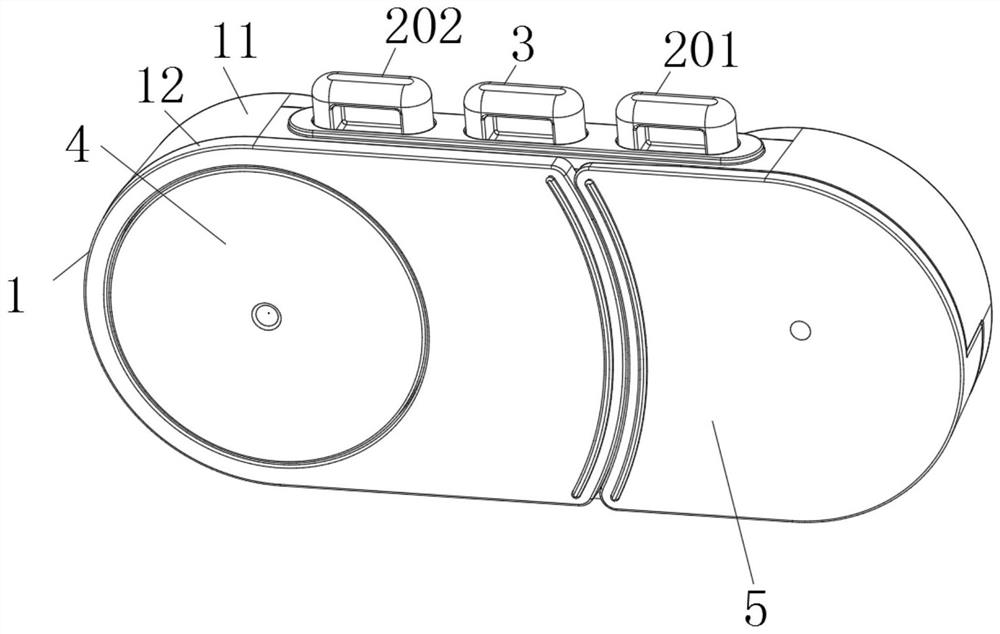
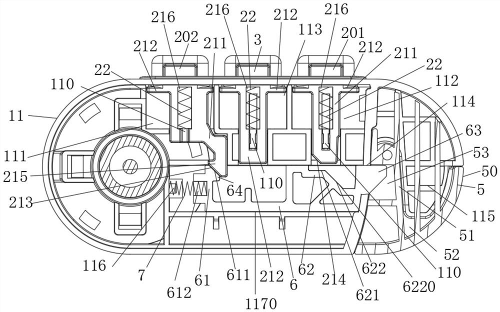
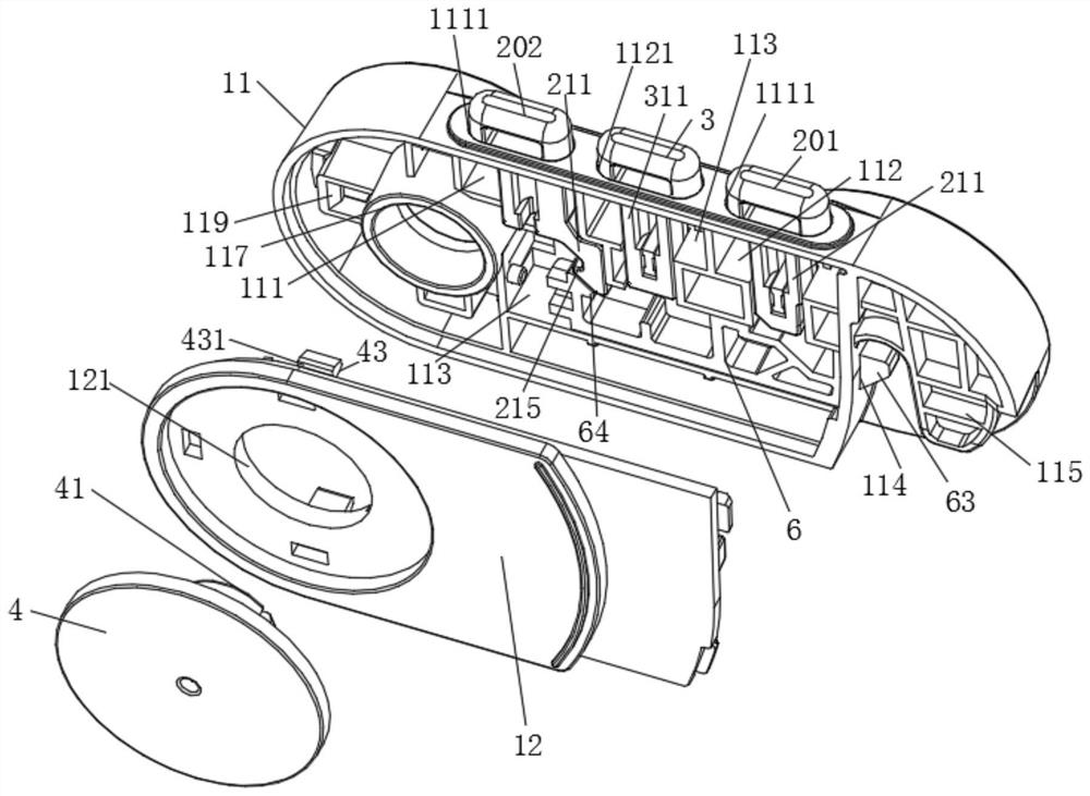
[0048] Such as Figure 1-Figure 6 As shown, the safety lock device described in this embodiment includes a first lock body 1 and a second lock body 50, a movable part 6 is arranged on the first lock body, and a lock head 63 located at one end of the movable part 6 moves from the first lock body One side of the body 1 protrudes and is inserted into the lock hole 53 of the second lock body 50 to lock the first lock body 1 and the second lock body 50 .

[0049] The first lock body 1 is equipped with a first moving part 201 and a second moving part 202, and the movable part 6 is provided with a first matching part 61 and a second matching part 61 respectively matched with the second moving part 202 and the first moving part 201. The fitting part 62 , the second fitting part 62 further includes a first unlocking part 621 and a second unlocking part 622 . When the first action piece 201 is matched with the first unlocking part 621, it cannot drive the action of the movable part 6 t...

Embodiment 2

[0060] The safety lock device described in this embodiment is roughly the same as that in Embodiment 1, the only difference being:

[0061] Such as Figure 7 As shown, the bottom of the first moving part 201 is a sloped part, and the first unlocking part 621 is set as a flat part. The moving part 201 can't drive the moving part 6 to move to unlock from the locking hole 53 at this time (that is, in the initial situation).

Embodiment 3

[0063] The safety lock device described in this embodiment is roughly the same as that in Embodiment 1, the only difference being:

[0064] As shown in FIG. 8 , the first unlocking portion 621 is configured to be composed of an inclined portion and a partition, the inclined portion is separated from the second unlocking portion 622 and is discontinuous, and the partition can separate the inclined portion of the first unlocking portion 621 and the partition. The second unlocking part 622 is a plane or a vertical surface, operating the first action part 201 alone can cause the movable part to produce a partial displacement under the action of the inclined part (not enough to make the movable part 6 unlock from the lock hole 53); and, After the second actuating part 202 cooperates with the first matching part 61 , it drives the movable part 6 to move correspondingly, so that the first actuating part 201 can change from cooperating with the first unlocking part 621 to cooperating w...


PUM


Abstract

The invention discloses a safety lock device and a control method thereof. The safety lock device comprises a first lock body and a second lock body; the first lock body is configured with a moving part; the first lock body comprises a first action member and a second action member; the moving part comprises a first matching member and a second matching member; the second matching member comprisesa first unlock part and a second unlock part; the second action member cooperates with the first matching member to drive the moving part to act, so that the first action member is matched with a second unlock part and not matched with a first unlock part; and the second action member is matched with the first matching member, and the moving part cannot be driven to be completely separated from akeyhole. The structure realizes the function that an individual action member cannot complete unlocking, and the two action members need to cooperate with each other to complete the unlocking function, and solves the current technical problems that children are easy to unlock and a door is easier to open, and potential safety hazards are caused.

Description

technical field [0001] The invention relates to a safety protection device, in particular to a safety lock device and a control method thereof. Background technique [0002] At present, children can easily open or close open doors or side-by-side sliding doors, but children generally have a weaker awareness of safety, and the hinges on the doors are usually closed automatically with a slight push device, so that when the child opens and then closes, the child's hand still stays between the door frame and the door or between the door and the door without any safety awareness, so that it is easy to pinch the child's hand, making the The safety performance of the use of the cabinet door is reduced, so there is an urgent need for a locking device for locking the above-mentioned type of door. Contents of the invention [0003] The object of the present invention is a safety lock device and an operation method of the safety lock device designed to solve the above technical defi...

Claims


Application Information

Patent Timeline
Patent Type & Authority Applications(China)
IPC IPC(8): E05B65/00E05B15/00E05B15/04
CPCE05B65/0014E05B15/00E05B15/04E05B2015/0448E05B37/163E05B9/02E05B37/16E05Y2900/20
Inventor 张珍陈映峰
Owner NINGBO EUDEMON CHILD PROTECTIVE EQUIP CO
Learn More