
Novel ward calling system

A call system and ward technology, applied in the field of medical management systems, can solve the problems of no information interaction between patients and HIS system, not knowing the specific reasons why patients ring the bell, and unfavorable protection of patients' privacy, so as to achieve a good rest environment and improve work efficiency. Efficiency and quality of work, improvement and effect on service quality

Pending Publication Date: 2020-11-06
山东大学齐鲁医院(青岛)
View PDF0 Cites 1 Cited by
  • Summary
  • Abstract
  • Description
  • Claims
  • Application Information

AI Technical Summary

Problems solved by technology

[0003] But in clinical practice, the existing ward call system and pager have the following defects: first, the call ringtone can be heard in the whole ward, which is not conducive to the rest of the patient, and is also not conducive to the construction of a quiet ward; When a patient calls, the whole ward can hear it clearly, which is not conducive to the protection of the patient's privacy. In addition, when the nurse is in the ward or corridor, he can hear the bell ringing intelligently, but he does not know the specific reason why the patient rings the bell. The nurse needs to go to the ward to see, and then Turning back the nursing car wastes manpower and nurses’ time, and reduces the work efficiency of nurses; similarly, if there are multiple bells calling at the same time, it is difficult to identify their respective positions in time, causing the medical staff to rush to the bedside in time; in addition to the above problems, Medical staff need to teach every morning, which is a waste of nurses' time, and patients can't remember it, which is not conducive to nurse-patient cooperation
The existing HIS system is mainly used for the internal personnel of the hospital, and there is no information interaction between patients and the HIS system

Method used


Image

  • Novel ward calling system
  • Novel ward calling system
  • Novel ward calling system

Examples


Embodiment Construction

[0028] The following will clearly and completely describe the technical solutions in the embodiments of the present invention with reference to the accompanying drawings in the embodiments of the present invention. Obviously, the described embodiments are only some, not all, embodiments of the present invention. Based on the embodiments of the present invention, all other embodiments obtained by persons of ordinary skill in the art without making creative efforts belong to the protection scope of the present invention.

[0029] In describing the present invention, it should be understood that the terms "center", "longitudinal", "transverse", "length", "width", "thickness", "upper", "lower", "front", " Back", "Left", "Right", "Vertical", "Horizontal", "Top", "Bottom", "Inside", "Outside", "Clockwise", "Counterclockwise", etc. or The positional relationship is based on the orientation or positional relationship shown in the drawings, and is only for the convenience of describing...


PUM


Abstract

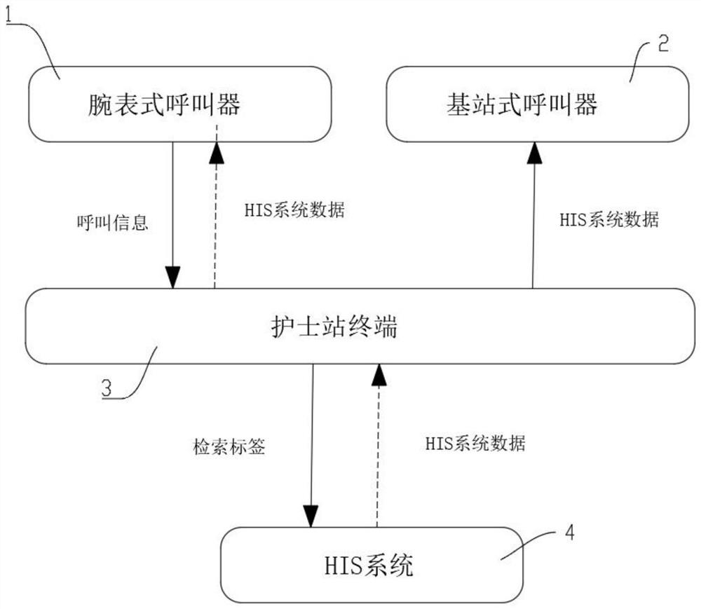
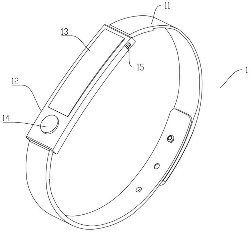
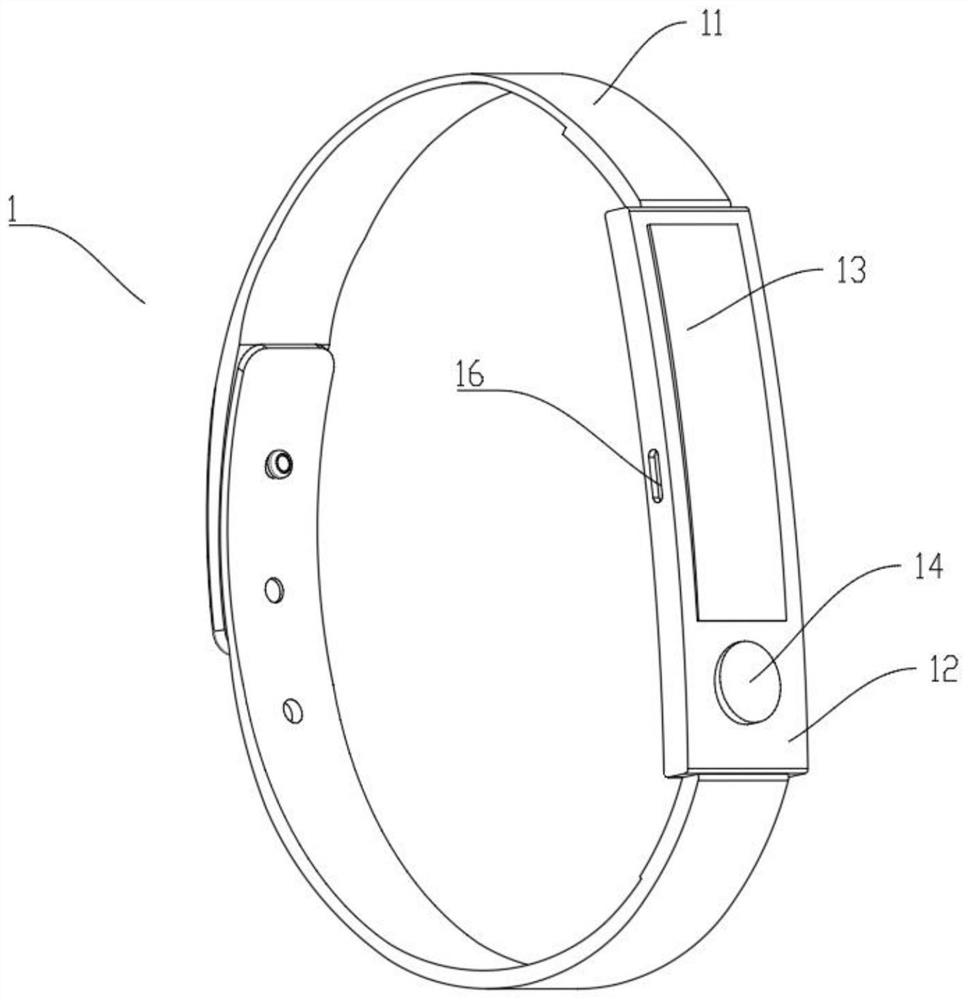
The invention provides a novel ward calling system, which comprises an HIS system and a nurse station terminal, the HIS system is interactively connected with the nurse station terminal, the output ofthe nurse station terminal is connected with a base station type calling device, and the nurse station terminal is interactively connected with a wristwatch type calling device. According to the invention, two calling devices are respectively arranged for a patient side and a medical worker side, information interaction of the two calling devices realizes information flow transmission through a nurse station terminal and an HIS system, so that key information can be read from the HIS system in time by means of position positioning and target retrieval of a calling end during calling, ie., theposition of a calling patient can be positioned in time, and information, bed position, basic cases, data of doctors and the like of the calling patient can be obtained; and the working efficiency and the working quality of medical staff are improved, a patient can conveniently use, and the safety of the patient is guaranteed.

Description

technical field [0001] The invention relates to the technical field of medical management systems, in particular to a novel ward calling system. Background technique [0002] The function of pagers in hospitals is common and important, especially in infusion rooms and inpatient wards. It is common for patients to seek nurses. When patients have needs, they can call nurses with one button, which can reduce the waiting time of patients, so that they can get Rescue in time, so pager has also become a kind of infrastructure of hospital, and hospital pager in the prior art has two kinds of wired intercom pager and wireless caller. [0003] But in clinical practice, the existing ward call system and pager have the following defects: first, the call ringtone can be heard in the whole ward, which is not conducive to the rest of the patient, and is also not conducive to the construction of a quiet ward; When a patient calls, the entire ward can hear it clearly, which is not conduciv...

Claims


Application Information

Patent Timeline
IPC IPC(8): G08B3/10
CPCG08B3/1016
Inventor 叶润泽
Owner 山东大学齐鲁医院(青岛)
Learn More