Push-and-pull switch capable of acting instantly

A technology of push-pull switch and action, which is applied in the field of push-pull switch with instantaneous action, which can solve problems such as electric tool burnout, hidden dangers to personal life safety, and insufficient connection and disconnection strokes, so as to reduce friction coefficient, increase agility, The effect of novel structure

Pending Publication Date: 2020-11-06
ZHEJIANG JIABEN ELECTRONICS CO LTD
View PDF0 Cites 0 Cited by
  • Summary
  • Abstract
  • Description
  • Claims
  • Application Information

AI Technical Summary

Problems solved by technology

[0003] 1. The commonly used push-pull switch is generally a shrapnel structure. The action of turning on and off the switch is not an instantaneous action, so the contact pressure is small when the switch is just turned on. If the switch passes a large current at this time, it will cause the silver contact of the switch. Point adhesion, in severe cases, the electric tool cannot be disconnected, does not meet the GB15092.1 standard, and poses a major safety hazard to personal life
[0004] 2. The commonly used push-pull switch is generally a shrapnel structure. The size of the shrapnel is not easy to control. Often, the switch feels bad and the on and off strokes are not in place. In severe cases, it will cause the electric tool to burn or even cause a fire. It also does not meet GB15092. 1 standard, there is a major safety hazard to personal life

Method used


Image

  • Push-and-pull switch capable of acting instantly
  • Push-and-pull switch capable of acting instantly
  • Push-and-pull switch capable of acting instantly

Examples


Embodiment Construction

[0047] The present disclosure will be described in detail below with reference to the embodiments and the accompanying drawings. It should be noted that the described embodiments are only intended to facilitate understanding of the present disclosure, rather than limiting it in any way. The orientations described in the present application, such as up, down, left, and right, are used for the convenience of describing with reference to the accompanying drawings, and do not constitute a limitation on the scope of protection.

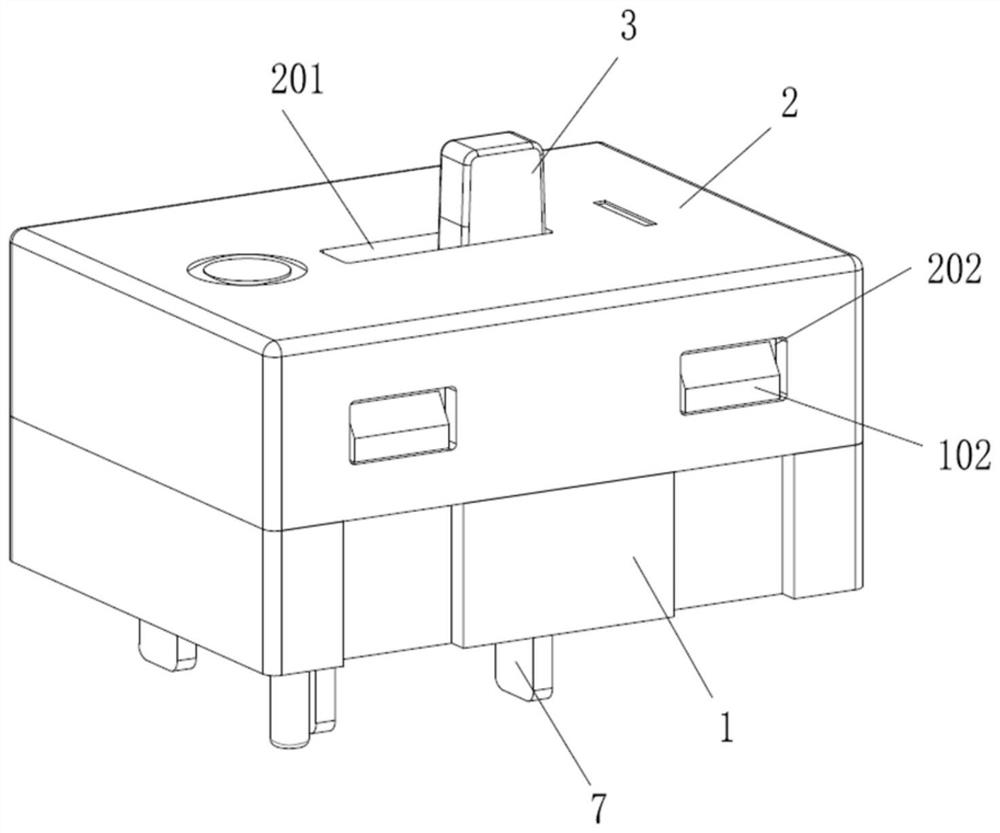
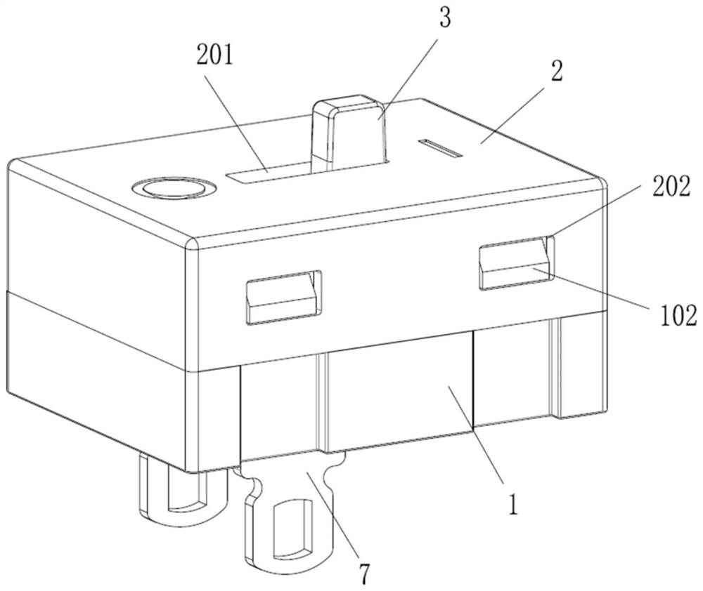
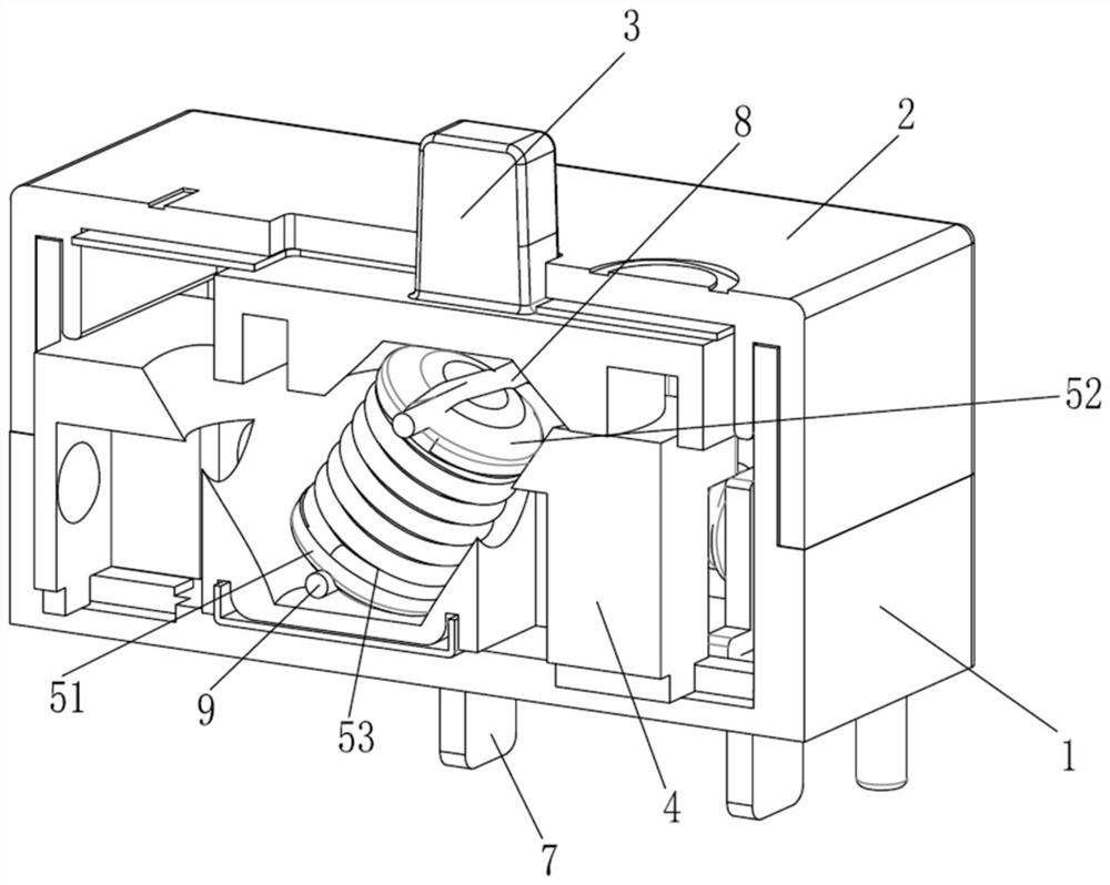
[0048] The present disclosure provides a momentary action push-pull switch, such as Figure 1-6 As shown, the push-pull switch includes a base body 1, a housing 2, a toggle button 3, and a movable contact slider 4 arranged between the toggle button 3 and the base body 1;

[0049] The shell 2 is provided with a toggle through hole 201, one end of the toggle 3 extends out of the box formed by the base body 1 and the shell 2 through the toggle through hole 20...


PUM


Abstract

The invention provides a push-and-pull switch capable of acting instantly. The push-pull switch comprises a base body, a shell, a toggle button and a moving contact sliding block arranged between thetoggle button and the base body, a toggle button through hole is formed in the shell, one end of the toggle button extends out of a box body formed by the base body and the shell through the toggle button through hole, and the other end of the toggle button is arranged in the box body; a middle shaft assembly is arranged between the toggle button and the moving contact sliding block, one end of the middle shaft assembly is connected to the toggle button, and the other end of the middle shaft assembly is connected to the moving contact sliding block; a moving contact assembly is arranged on themoving contact sliding block, and a static contact assembly matched with the moving contact assembly is arranged on the base body. When the switch is just turned on, the contact pressure of the contacts is large, the contact pressure does not change along with the change of the stroke of the switch, when a large current passes through the switch, adhesion of the silver contacts of the switch is not caused, and meanwhile, the structure enables the switch to act instantly.

Description

technical field [0001] The present disclosure relates to a push-pull switch, in particular to a momentary-action push-pull switch. Background technique [0002] The push-pull switches currently on the market have the following functional defects: [0003] 1. The commonly used push-pull switch is generally a shrapnel structure. The action of turning on and off the switch is not an instantaneous action, so the contact pressure is small when the switch is just turned on. If the switch passes a large current at this time, it will cause the silver contact of the switch. In severe cases, the power tool cannot be disconnected, which does not meet the GB15092.1 standard and poses a major safety hazard to personal life. [0004] 2. The commonly used push-pull switch is generally a shrapnel structure. The size of the shrapnel is not easy to control. Often, the switch feels bad and the on and off strokes are not in place. In severe cases, it will cause the electric tool to burn or eve...

Claims


Application Information

Patent Timeline
Patent Type & Authority Applications(China)
IPC IPC(8): H01H15/18H01H15/10H01H15/02
CPCH01H15/02H01H15/10H01H15/18
Inventor 倪圣珑
Owner ZHEJIANG JIABEN ELECTRONICS CO LTD
Why Eureka
Try Eureka