
Method of calibrating a gyrometer installed in a vehicle

A gyroscope and vehicle technology, applied to gyroscope/steering sensing equipment, gyro effect for speed measurement, instrument and other directions, can solve problems such as limitation, unrecognizable scale factor, acceleration, etc.

Pending Publication Date: 2020-11-06
SYSNAV
View PDF15 Cites 0 Cited by
  • Summary
  • Abstract
  • Description
  • Claims
  • Application Information

AI Technical Summary

Problems solved by technology

[0019] This approach is simple and effective, but has proven restrictive since it relies on the straight line
Moreover, in practice it is not enough for the trajectory to be on a straight line, it must also not be able to accelerate too strongly, a straight line without acceleration can only recognize the deviation of the gyroscope, but not the scale factor

Method used


Image

  • Method of calibrating a gyrometer installed in a vehicle
  • Method of calibrating a gyrometer installed in a vehicle

Examples


Embodiment Construction

[0049] architecture

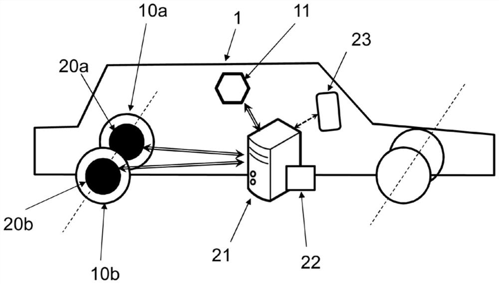
[0050] refer to figure 2, this method can calibrate the gyroscope 11 (ie, the inertial measurement device capable of measuring the angular velocity of the vehicle 1 ) equipped with the vehicle 1 . The vehicle is also equipped with means 20 for measuring at least one other quantity representative of the angular velocity of the vehicle 1 .

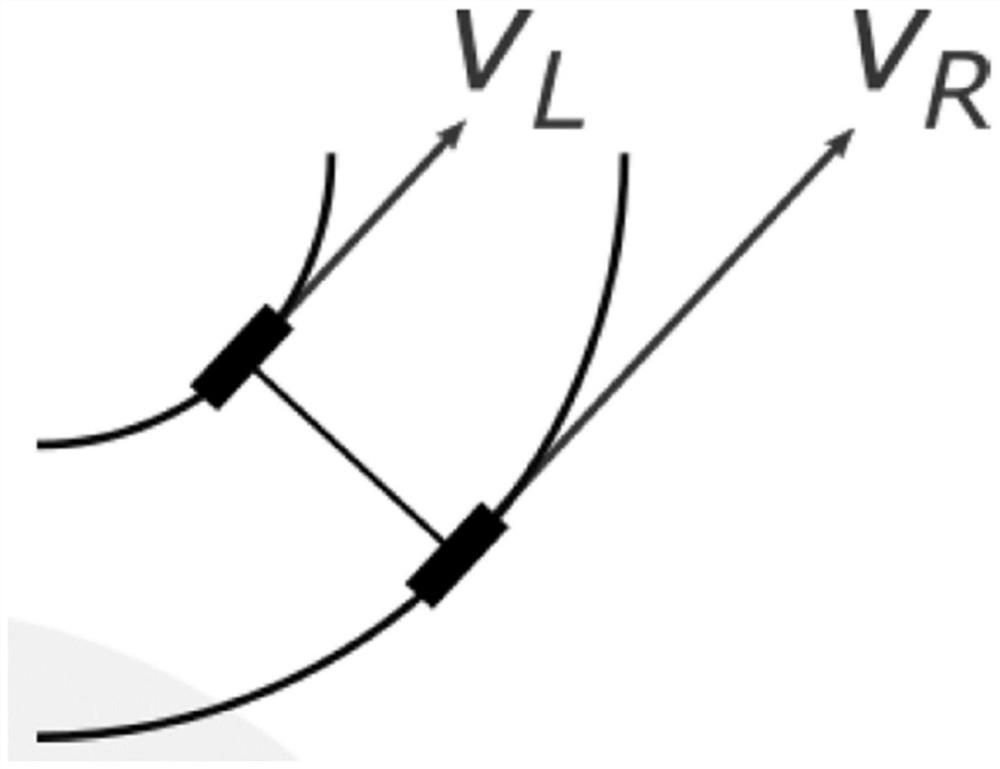
[0051] It should be understood that the device 20 may be any sensor integrated with the vehicle 1 instead of a gyroscope, which makes it possible to obtain the angular velocity indirectly. Said measuring means 20 thus advantageously comprise an angular steering wheel sensor (the at least one quantity representing the angular velocity of the vehicle 1 is the angle of the steering wheel relative to a reference position of the vehicle 1 traveling in a straight line), and / or at least two odometers 20a , 20b, that is, the vehicle 1 has at least two wheels 10a, 10b, and each wheel is provided with an odometer 20a, 20b (the...


PUM


Abstract

The invention relates to a method of calibrating a gyrometer (11) installed in a vehicle (1), said method being characterised in that it comprises the following steps: (a) acquiring, using the gyrometer (11), a measured angular velocity of the vehicle (1) and, using means (20) for measuring at least one magnitude that is representative of the angular velocity of the vehicle (1), acquiring measuredvalues of said at least one magnitude that is representative of the angular velocity of the vehicle (1); and (b) determining, using data processing means (21), values of at least one parameter for calibrating the gyrometer (11), minimising a gap between a first estimated angular velocity of the vehicle (1) and a second estimated angular velocity of the vehicle (1), wherein - the first estimated angular velocity of the vehicle (1) is a function of the measured angular velocity and calibration parameters of the gyrometer (11), and - the second estimated angular velocity of the vehicle (1) is afunction of the measured values of the at least one magnitude that is representative of the angular velocity of the vehicle (1).

Description

technical field [0001] The invention relates to the field of navigation without GNSS. [0002] More specifically, the present invention relates to a method for calibrating a gyroscope equipped with a vehicle equipped with an odometer. Background technique [0003] Today it is common to track vehicle position via GNSS (Global Navigation Satellite System, e.g. GPS) or using communication networks (triangulation using transmitter terminals, Wi-Fi networks, or others). [0004] These methods have proven to be very limited as they do not work indoors, in tunnels or too far from the transmitter and have been shown to rely on external technologies such as satellites for GNSS which may not be available , even automatically scrambled. [0005] Alternatively, "autonomous" methods are also known for tracking the relative displacement of the vehicle in any environment using inertial or magneto-inertial units. Relative displacement refers to the fixed trajectory given by the vehicle r...

Claims


Application Information

Patent Timeline
Patent Type & Authority Applications(China)
IPC IPC(8): G01C19/00G01C25/00G01C22/02
CPCG01C19/00G01C22/025G01C25/005G01C21/165
Inventor 大卫·维西埃马蒂厄·希尔伊恩昂德里克·迈耶让-菲力浦·杜加尔德
Owner SYSNAV
Learn More