Nursing medicine feeding device

A technology of mounting plates and bases, which is applied in the medical field, can solve problems affecting the health of patients, difficulty in taking medicine independently, and muscle atrophy of legs, etc., and achieves the effect of facilitating medicine feeding, slowing down muscle atrophy, and improving comfort

Inactive Publication Date: 2020-11-10
姜永杰
View PDF7 Cites 6 Cited by
  • Summary
  • Abstract
  • Description
  • Claims
  • Application Information

AI Technical Summary

Problems solved by technology

[0002] At present, due to the particularity of critically ill patients in clinical practice, it is often difficult for paralyzed critically ill patients to take medicine, and it is dif

Method used


Image

  • Nursing medicine feeding device
  • Nursing medicine feeding device
  • Nursing medicine feeding device

Examples


Embodiment 1

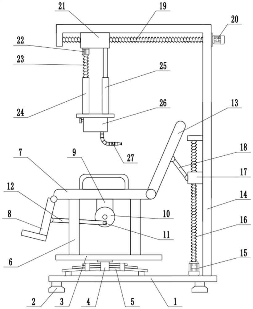
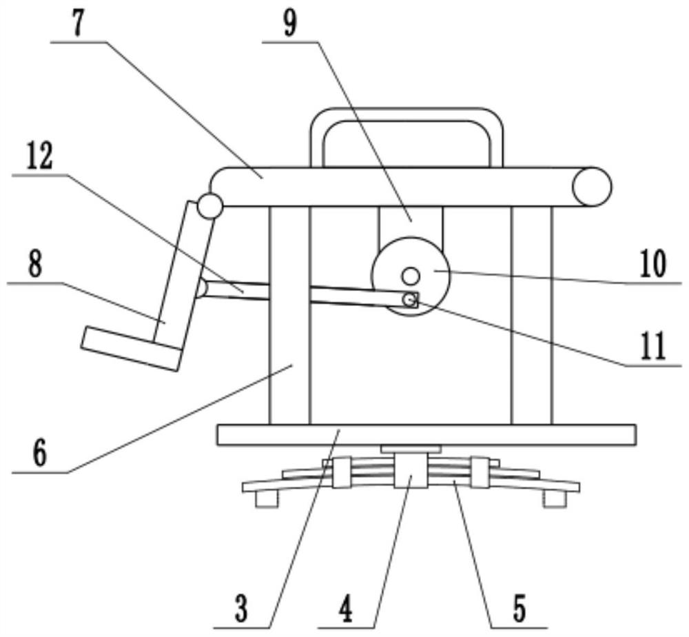
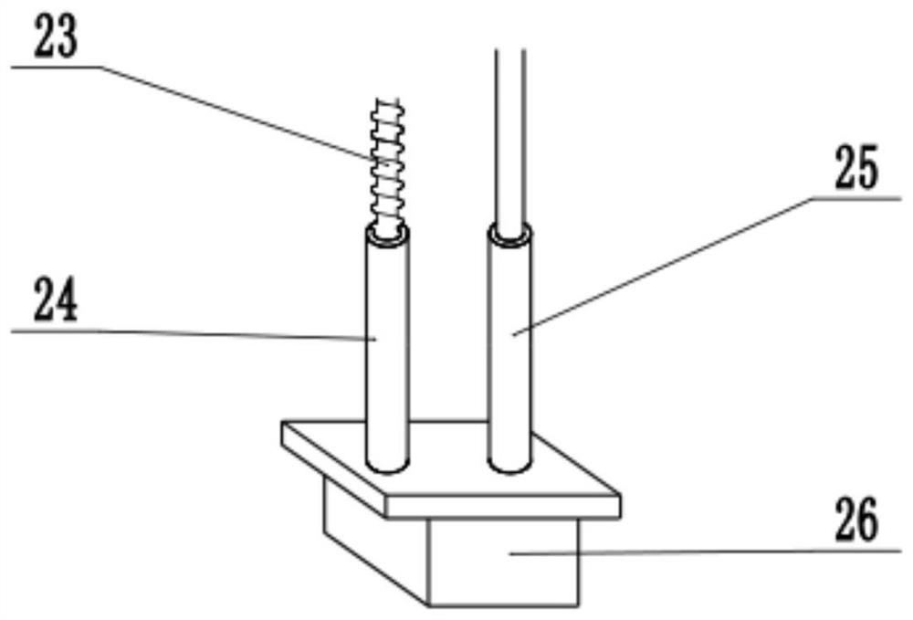
[0021] see Figure 1-3 , in an embodiment of the present invention, a nursing medicine feeding device includes a base 1, chair legs 6, a chair surface 7, a fixing frame 14, a medicine tank 26 and a medicine feeding tube 27, and the bottom of the base 1 is fixedly connected with a foot 2 , the top of the base 1 is provided with a mounting plate 3, the lower surface of the mounting plate 3 is fixedly connected with a mounting frame 4, the mounting frame 4 is fixedly connected with a leaf spring 5, and the two ends of the leaf spring 5 are connected to the upper surface of the base 1 connection, using the plate spring 5 can play a role in shock absorption, reducing the vibration generated by the device during use, the upper surface of the mounting plate 3 is fixedly connected with the chair leg 6, and the top of the chair leg 6 is fixedly connected with the chair surface 7, One end of the chair surface 7 is hinged with a pedal bracket 8, the bottom of the chair surface 7 is fixed...

Embodiment 2

[0023] On the basis of Embodiment 1, the upper surface of the base 1 is fixedly connected with a second motor 15, the second motor 15 is a forward and reverse motor, and the shaft extension end of the second motor 15 is fixedly connected with an adjusting screw 16, and the adjusting screw The rod 16 is provided with a lifting block 17, the lifting block 17 is slidably connected with the side wall of the fixed frame 14, the lifting block 17 is hinged with a support rod 18, and the free end of the support rod 18 is hinged with the side wall of the chair back 13 to control the first seat back. Two motors 15 forward and reverse can drive the adjustment screw mandrel 16 forward and reverse, thereby drive the lifting block 17 to move up and down, and then adjust the inclination angle of the chair back 13 by the support rod 18, which is very convenient.

[0024] In combination with Embodiment 1 and Embodiment 2, the working principle of the present invention is: the liquid medicine ta...


PUM


Abstract

The invention relates to the technical field of medical treatment, in particular to a nursing medicine feeding device. The nursing medicine feeding device comprises a base, chair legs, a chair surface, a fixing frame, a liquid medicine tank and a medicine feeding pipe, wherein a mounting plate is arranged above the base; the chair legs are fixedly connected to the upper surface of the mounting plate; the chair surface is fixedly connected to the tops of the chair legs; the fixing frame is fixedly connected to the upper surface of the base; a translation lead screw is installed at the top of the fixing frame; a sliding block is arranged on the translation lead screw in a sleeving mode; the lower surface of the sliding block is fixedly connected with a fourth motor; the shaft extension end of the fourth motor is fixedly connected with a lifting lead screw; the lower end of the lifting lead screw is sleeved with a sleeve which is in threaded connection with the lifting lead screw; the lower end of the sleeve is fixedly connected with the liquid medicine tank; and the medicine feeding pipe is installed at the bottom of the liquid medicine tank. A patient sits on the chair surface, andthe legs of the patient can be driven to swing through the first motor, so that rehabilitation training of the legs of the patient is facilitated; and the position and height of the liquid medicine tank can be adjusted by controlling the liquid medicine tank to move vertically and horizontally.

Description

technical field [0001] The invention relates to the field of medical technology, more specifically, a nursing medicine feeding device. Background technique [0002] At present, due to the particularity of critically ill patients clinically, paralyzed critically ill patients often have difficulty taking medicine and taking medicine independently, and paralyzed patients often lack leg exercises, which may easily cause leg muscle atrophy and affect the patient's health. Contents of the invention [0003] The purpose of the present invention is to provide a nursing medicine feeding device to solve the problems raised in the above-mentioned background technology. [0004] To achieve the above object, the present invention provides the following technical solutions: [0005] A nursing medicine feeding device, comprising a base, a chair leg, a chair surface, a fixed frame, a medicine tank and a medicine feeding tube, a mounting plate is arranged above the base, and a chair leg i...

Claims


Application Information

Patent Timeline
IPC IPC(8): A61G15/04A61G15/10A61G15/12A61H1/02A61J7/00
CPCA61G15/02A61G15/10A61G15/12A61H1/0237A61J7/0053A61H2201/0149A61H2201/1207A61H2201/1642A61H2205/10A61H2201/0165
Inventor 姜永杰姜永华姜永梅
Owner 姜永杰
Why Eureka
Try Eureka