Power head damper and rotary drilling rig

A shock absorber and power head technology, applied in rotary drilling rigs, springs/shock absorbers, rotary drilling, etc. The thickness of the limit block 10 and other issues can reduce the impact of the impact

Pending Publication Date: 2020-11-10
SHANGHAI ZOOMLION HEAVY IND PILING MACHINERYCO
View PDF1 Cites 0 Cited by
  • Summary
  • Abstract
  • Description
  • Claims
  • Application Information

AI Technical Summary

Problems solved by technology

First of all, due to actual processing problems, it will be difficult to process threaded holes on the circumference, which will affect the assembly results
Secondly, the construction condition of the rotary drilling rig is poor, and the bolt assembly structure will cause loose bolts for a long time
Furthermore, since the design gap between the platen cylinder 17 and the base cylinder 34 is relatively small, this structure fails to increase the thickness of the limiting partition 12 and the limiting block 10
Finally, the above-mentioned damping mechanism of the power head uses a nitrogen spri

Method used


Image

  • Power head damper and rotary drilling rig
  • Power head damper and rotary drilling rig
  • Power head damper and rotary drilling rig

Examples


Example

[0035] [First Embodiment]

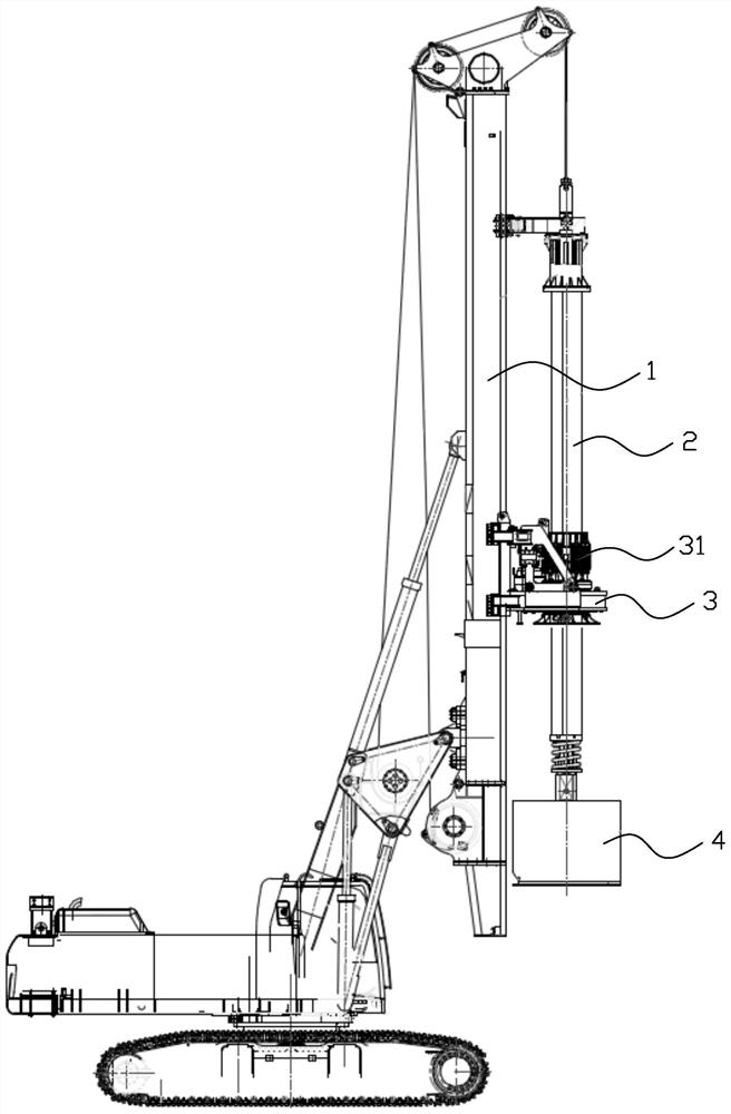
[0036] like figure 1 As shown, the rotary drilling rig includes a main engine and a mast 1, a drill pipe 2, a power head assembly 3 and a drilling tool 4 arranged on the main engine. The bottom of the mast 1 is pivotally connected to the main engine, so that the mast 1 can be opened to a substantially vertical state during construction of the rotary drilling rig, or folded to the main engine during shutdown. The power head assembly 3 is arranged on the mast, and is connected with the main engine through a pressurized oil cylinder or a pressurized hoisting wire rope. The drill rod 2 is connected with the power head assembly 3 to rotate under the driving of the power head assembly 3 . The drilling tool 4 is installed at the bottom of the drill rod 2 and can be driven by the drill rod 2 to perform drilling operations. The main engine is also provided with a cab, a main hoisting device, etc., which are well known to those skilled in the art and will ...

Example

[0055] [Second Embodiment]

[0056] Please also refer to Figure 13 and Figure 14 , the power head shock absorber 31 of this embodiment is substantially the same as the power head shock absorber 31 of the first embodiment, the difference is that the first guide portion 3231 only has two limiting portions 3231b, and the two limiting portions 3231b are respectively fixed on both sides of the installation port 3232, each limiting portion 3231b and the bracket body 323a of the shock absorber bracket 323 connected to it are roughly “T” shaped, and the space between the two limiting portions 3231b A guide groove 3231c is formed.

[0057] For other structures of this embodiment, please refer to the above-mentioned first embodiment, which will not be repeated here.

[0058] The beneficial effect of the power head shock absorber of the present invention is that the power head shock absorber includes a shock absorber bracket and a drive sleeve, and the shock absorber bracket is slee...


PUM


Abstract

The invention discloses a power head damper. The power head damper comprises a damper support and a driving sleeve, and the damper support is arranged on the driving sleeve in a sleeving manner. The damper support comprises a cylindrical support body and a plurality of first guide parts arranged on the support body, a plurality of installation openings are formed in the support body in the circumferential direction at intervals, each installation opening is provided with one first guide part, each first guide part is provided with a guide groove with an opening facing the driving sleeve, and the extending direction of the guide grooves is the same as the axial direction of the support body. The driving sleeve comprises a base and a driving sleeve body connected with the base, a plurality of second guide parts are arranged at the upper end, away from the base, of the driving sleeve body, and each second guide part is clamped in one guide groove and can slide up and down along the guidegroove. A guide structure of the power head damper is high in strength, can protect guide rods, springs and the like from being impacted under the unbalance loading reducing condition, does not need to be assembled through bolts, does not have the bolt loosening phenomenon, and is firm and durable. The invention further relates to a rotary drilling rig.

Description

technical field [0001] The invention relates to the technical field of engineering machinery, in particular to a power head shock absorber and a rotary drilling rig provided with the power head shock absorber. Background technique [0002] Rotary drilling rig is a modern large-scale mechanical equipment with electromechanical and hydraulic integration used for hole forming in pile foundation engineering, with strong operation cycle. A rotary drilling rig usually includes a main engine, a mast, a drill pipe, a power head and a drilling tool arranged on the main engine. Wherein, the bottom of the mast is pivotally connected to the main engine. The power head is set on the mast and is connected with the main engine through a pressurized oil cylinder or a pressurized hoisting wire rope. The drill pipe is connected with the power head through the key sleeve to rotate under the drive of the power head. The drilling tool is installed at the bottom of the drill pipe and can be dr...

Claims


Application Information

Patent Timeline
IPC IPC(8): E21B3/02F16F15/04F16F15/06F16F15/023
CPCE21B3/02F16F15/023F16F15/046F16F15/06
Inventor 刘国莉杨涛金洲徐苾璇黄利云
Owner SHANGHAI ZOOMLION HEAVY IND PILING MACHINERYCO
Why Eureka
Try Eureka