
A continuous reforming reactor sealing device for reforming liquefied gas production

A technology for reforming reactors and sealing devices, applied in chemical instruments and methods, chemical/physical processes, chemical/physical/physicochemical processes, etc., can solve problems such as deformation, support structure can not evenly share gravity, etc., to achieve the use Convenient, eliminate safety hazards, and high stability

Active Publication Date: 2020-12-22
东营威联化学有限公司
View PDF7 Cites 0 Cited by
  • Summary
  • Abstract
  • Description
  • Claims
  • Application Information

AI Technical Summary

Problems solved by technology

The reforming device can be roughly divided into two categories: semi-regenerative reforming and continuous reforming. The scale of continuous reforming is relatively large, and the reactors are all radial reactors. Among them, the sealing cover plate is to ensure that the material flows along the correct flow path. During the construction process, the key components of circulation are easily deformed due to the gravity of workers and equipment, and the simple support structure cannot evenly share its gravity

Method used


Image

  • A continuous reforming reactor sealing device for reforming liquefied gas production
  • A continuous reforming reactor sealing device for reforming liquefied gas production
  • A continuous reforming reactor sealing device for reforming liquefied gas production

Examples


Embodiment Construction

[0016] In order to make the purpose, technical solutions and advantages of the embodiments of the present invention clearer, the technical solutions in the embodiments of the present invention will be clearly and completely described below in conjunction with the drawings in the embodiments of the present invention. Obviously, the described embodiments It is a part of embodiments of the present invention, but not all embodiments. Based on the embodiments of the present invention, all other embodiments obtained by persons of ordinary skill in the art without creative efforts fall within the protection scope of the present invention.

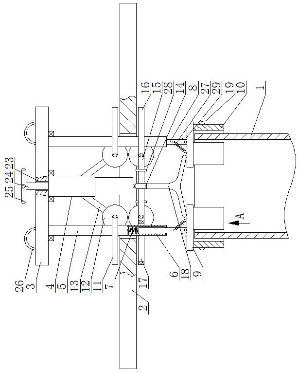
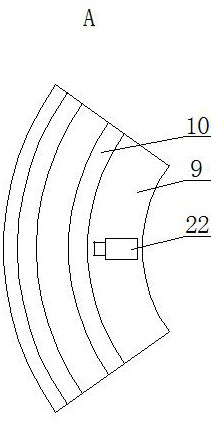
[0017] A continuous reforming reactor sealing device for reforming liquefied gas production, as shown in the figure, includes a central pipe 1 and a sealing plate 2, the sealing plate 2 is an annular structure for the expansion coil connected to the central pipe 1 to pass through it After that, the catalyst feed pipe can be opened and sealed on th...


PUM


Abstract

The utility model discloses a continuous reforming reactor sealing device for producing reformed liquefied gas. The device comprises a central pipe and sealing plates, the sealing plate is of an annular structure, a supporting plate parallel to the sealing plate is arranged above the sealing plate, the bottom surface of the supporting plate is rotationally connected with the upper end of a telescopic rod, supporting rods are arranged on the two sides of the bottom face of the supporting plate respectively and can rotate with the telescopic rod as the center at the same time, blind holes are formed in the lower ends of the supporting rods, the upper ends of the blind holes are fixedly connected with the upper ends of first tension springs, the lower ends of the first tension springs are fixedly connected with the upper ends of movable rods, and the movable rods are located in the corresponding blind holes and are in sliding fit. The device can more stably support the installation of thesealing plate, through mutual cooperation of the arc-shaped plate, the first clamping plate and the second clamping plate, the sealing plate and the center pipe can be tightly connected, the sealingplate is prevented from moving in the installation process, potential safety hazards are eliminated, the gravity of the sealing plate and people and objects on the sealing plate can be more evenly shared, and the hidden danger of local deformation of the inner ring of the sealing plate and the top of the center pipe is eliminated.

Description

technical field [0001] The invention belongs to the field of reforming reactors, in particular to a continuous reforming reactor sealing device for reforming liquefied gas production. Background technique [0002] With the shortage of oil resources at home and abroad and the deterioration of crude oil, the demand for light oil and middle distillates continues to increase, which puts forward higher requirements for the quality of petroleum products. The oil refining industry must provide more environmentally friendly fuels to the society. Under this development trend, the adoption of catalytic reforming process is imperative. The reforming device can be roughly divided into two categories: semi-regenerative reforming and continuous reforming. The scale of continuous reforming is relatively large, and the reactors are all radial reactors. Among them, the sealing cover plate is to ensure that the material flows along the correct flow path. During the construction process, the ...

Claims


Application Information

Patent Timeline
Patent Type & Authority Patents(China)
IPC IPC(8): B01J19/00
CPCB01J19/0073
Inventor 马海峰王浩然李西春齐世森李广凯李云霄
Owner 东营威联化学有限公司
Learn More