
Shipborne boat swing rod type catching and releasing device, shipborne boat and mother boat

A release device, ship-borne technology, applied in the direction of ships, ship safety, transportation and packaging, etc., can solve problems such as impact, failure to release the boat, and heavy workload.

Pending Publication Date: 2020-11-13
广州船舶及海洋工程设计研究院(中国船舶集团有限公司第六〇五研究院)
View PDF0 Cites 2 Cited by
  • Summary
  • Abstract
  • Description
  • Claims
  • Application Information

AI Technical Summary

Problems solved by technology

However, for the crane lifting type and the flushing and discharging slideway type, manual assistance is required to carry out corresponding binding or loosening each time the ship-borne boat is retracted and locked, which is inconvenient, heavy workload, and low efficiency. Although the harpoon-type catching hook and rod combination device has realized the function of fast, safe and automatic catching, it has also exposed defects as the functional expansion of ship-borne boats and the increase in the demand for multi-boat continuous retraction. : The size of the catching hook is too large, which affects the arrangement of other functional equipment on the bow of the ship-borne boat (such as the arrangement of measuring devices or other equipment); the matching catching rod on the boat frame or tow frame also needs a corresponding height and structure support, and the catching hook and the catching rod are in rigid contact. If the ship-borne boat is not in the water, the catching hook and the catching rod will be difficult to disengage, resulting in the failure of launching the boat, so it cannot meet the needs of continuous retracting and launching of multiple boats

Method used


Image

  • Shipborne boat swing rod type catching and releasing device, shipborne boat and mother boat
  • Shipborne boat swing rod type catching and releasing device, shipborne boat and mother boat
  • Shipborne boat swing rod type catching and releasing device, shipborne boat and mother boat

Examples


Embodiment Construction

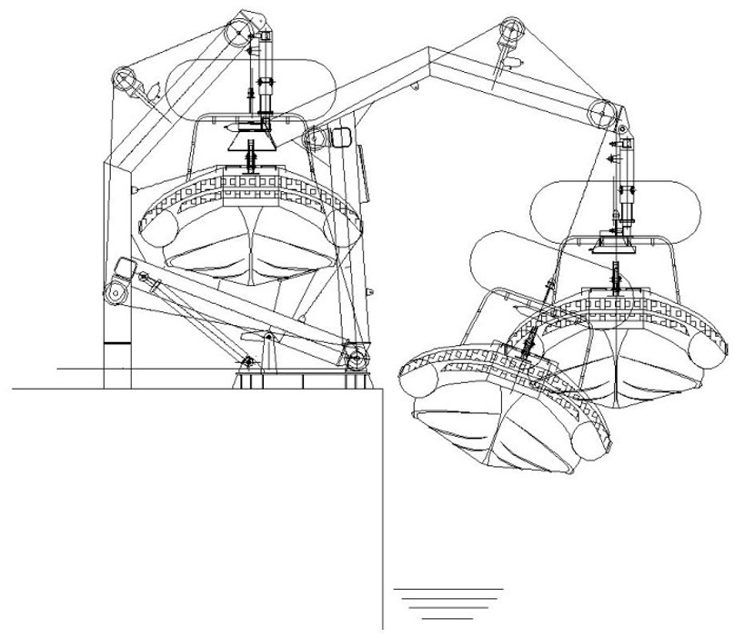
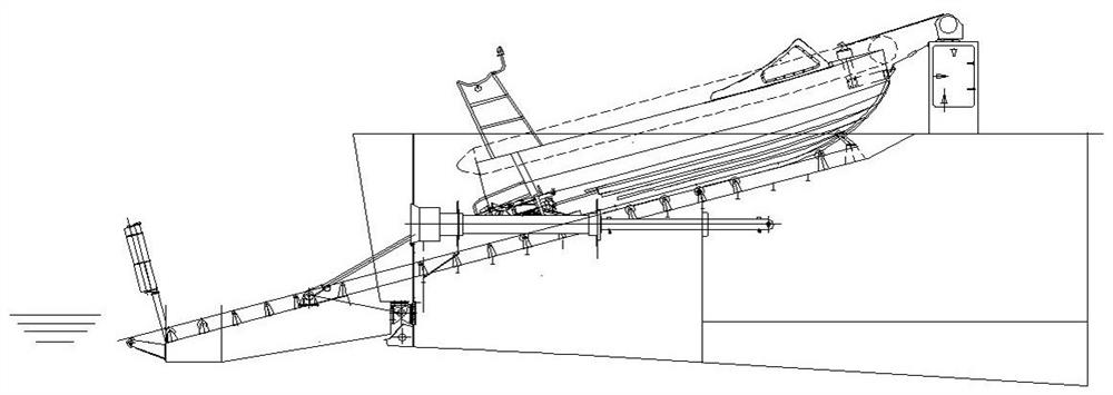
[0018] A ship-borne pendulum-type catch-and-release device, such as Figure 4 to Figure 16 As shown, it includes a catching hook assembly and a catching net assembly respectively installed on the ship-borne boat and the mother ship; the catching hook assembly 1 includes a hook body 11 in the shape of an arrow, and two hooks at the widest position of the head of the hook body 11 A swing rod 12 is hinged symmetrically at each end, and the other ends of the two swing rods 12 are all connected to the driving structure that drives them to swing synchronously; The spacing between is less than the maximum width of the hook body 11 head, so that after the head of the hook body 11 passes through the adjacent arresting rope 21 on the catch net 2, the adjacent arresting rope 21 can lock the hook body 11 head and limit. The head of the hook body 11 is preferably perpendicular to the arresting rope 21 of the catch net assembly 2 after passing through the catch net assembly 2 . Multiple a...


PUM


Abstract

The invention discloses a shipborne boat swing rod type catching and releasing device, a shipborne boat and a mother boat. The catching hook assembly is simple and compact in structure; a capturing hook can be installed on a stem or a bow deck of the shipborne boat through a capturing hook fixing base. Arrangement of various functional devices on the shipborne boat is not affected, a number of arresting ropes are arranged on a catching net at intervals, the catching hook assembly can match any two adjacent arresting ropes on the catching net, the catching net does not need to be specially required to have the corresponding height and structural support, and wide installation and application range and high universality of the catching net are further reflected. Through cooperation of the rigid catching hook assembly and the flexible catching net, flexible collision is achieved, a large error-tolerant rate can be achieved by arranging a plurality of loose arresting ropes, and effective catching of the shipborne boat is ensured; by means of the structure, continuous folding and unfolding of multiple boats can be achieved, and the folding and unfolding efficiency is high.

Description

technical field [0001] The invention relates to a ship-borne boat pendulum-type capture and release device, a ship-borne boat and a mother ship. Background technique [0002] In order to make up for the inability of large ships to navigate in shallow waters or narrow waters and special needs, it has become more and more common to configure fast shipboard boats (including manned work boats and unmanned boats) with flexible performance on large ships. These shipboard boats must be able to meet the requirements of simple, safe and fast retraction from large ships. During the retraction operation, it is usually necessary to lock these shipboard boats and align them to effectively limit them so that the shipboard boats can be fixed. Carry out operations such as towing, hoisting, and transfer on the stern slide or gondola of large ships. At present, the capture methods for ship-borne boats include: 1. Crane lifting type, where single-point or multi-point lifting rings or hooks ar...

Claims


Application Information

Patent Timeline
IPC IPC(8): B63B23/00
CPCB63B23/00
Inventor 黎理胜卢孝武陈海光杨涛李光天何伟群
Owner 广州船舶及海洋工程设计研究院(中国船舶集团有限公司第六〇五研究院)
Learn More