Test tube cleaning device

A technology for cleaning devices and test tubes, applied in the direction of cleaning hollow objects, cleaning methods and utensils, chemical instruments and methods, etc., can solve problems such as low safety, poor cleaning effect, time-consuming and laborious, etc., and achieve the effect of improving cleaning efficiency

Pending Publication Date: 2020-11-17
郑稳翠
View PDF0 Cites 8 Cited by
  • Summary
  • Abstract
  • Description
  • Claims
  • Application Information

AI Technical Summary

Problems solved by technology

[0004] In order to overcome the shortcomings of the existing test tube cleaning methods, such as time-consuming, labor-intensive, poor cleaning effect, and low safety, the technical problem to be solved is:

Method used


Image

  • Test tube cleaning device
  • Test tube cleaning device
  • Test tube cleaning device

Examples


Embodiment 1

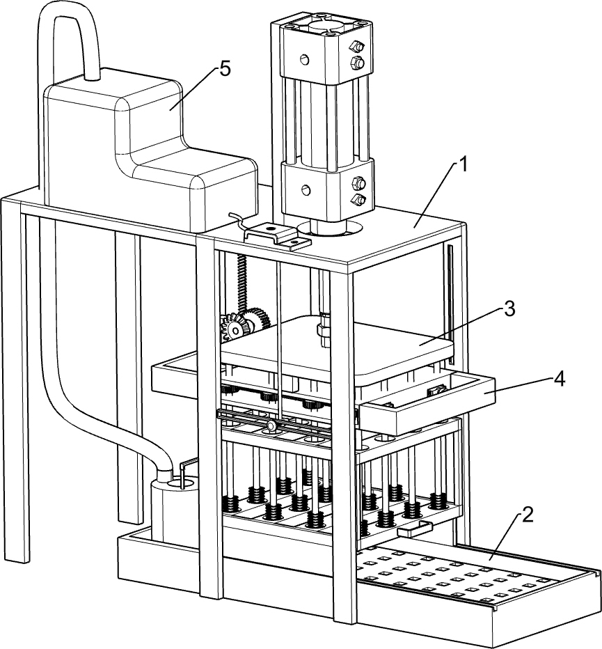
[0022] A test tube cleaning device, such as figure 1 As shown, it includes a mounting frame 1, a placement mechanism 2, a lifting cleaning mechanism 3, and a rotating mechanism 4. A placement mechanism 2 is provided between the lower right part of the mounting frame 1, and a lifting cleaning mechanism 3 is connected to the upper right side of the mounting frame 1. , The lower side of the lifting and cleaning mechanism 3 is provided with a rotating mechanism 4, and the rotating mechanism 4 is connected with the inner top wall of the mounting frame 1.

[0023] When the device needs to be used, people can start the parts of the lifting and cleaning mechanism 3, drive the parts of the lifting and cleaning mechanism 3 to move upward to the top of the placement mechanism 2, close the parts of the lifting and cleaning mechanism 3, and slide the parts of the placement mechanism 2 to the right, Place the test tube in the placement mechanism 2, slide the parts of the placement mechanism...

Embodiment 2

[0025] On the basis of Example 1, such as Figure 1-3 As shown, the placement mechanism 2 includes a placement frame 21 and a test tube rack 22. The placement frame 21 is arranged between the lower right part of the installation frame 1, and the test tube rack 22 is slidably connected between the front and rear sides of the top of the placement frame 21.

[0026] When the test tube needs to be placed, people can start the parts of the lifting and cleaning mechanism 3, drive the parts of the lifting and cleaning mechanism 3 to move upwards to the top of the test tube rack 22, close the parts of the lifting and cleaning mechanism 3, slide the test tube rack 22 to the right, and place the test tube In the test tube rack 22, slide the test tube rack 22 to the left to reset.

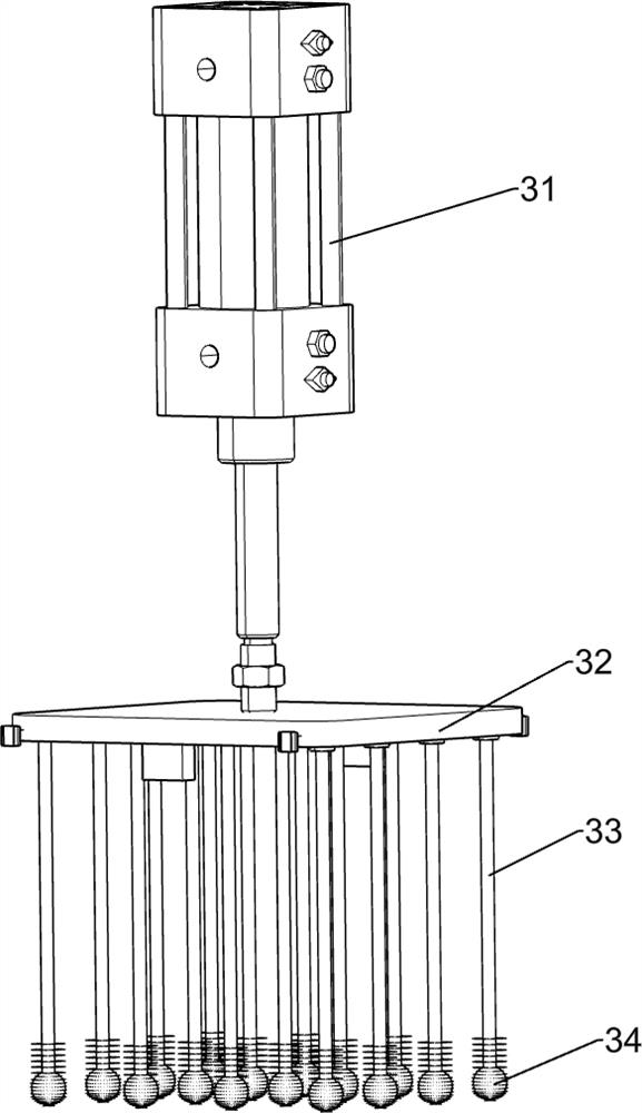
[0027] The lifting and cleaning mechanism 3 includes a cylinder 31, a lifting plate 32, a connecting rod 33 and a hairbrush 34, the upper side of the right side of the mounting frame 1 is provided with a cyli...

Embodiment 3

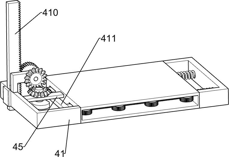
[0030] On the basis of Example 2, such as figure 1 with Figure 4-6 As shown, the rotating mechanism 4 includes a mounting frame 41, a double-sided rack 42, an elastic member 43, a first gear 44, a connecting plate 45, a first bevel gear 46, a cam 47, a second bevel gear 48, and a second gear 49 , a single-sided rack 410, a slider 411, a first shaft 412 and a second shaft 413, an installation frame 41 is connected between the front and rear sides of the bottom of the lifting plate 32, the connecting rods 33 pass through the installation frame 41, and inside the installation frame 41 Slide block 411 is connected to the left sliding type, and double-sided rack 42 is provided on the front and rear sides of the right part of slide block 411, and elastic member 43 is connected between the right side of double-sided rack 42 and the inner right wall of installation frame 41, The upper part of the connecting rod 33 is equipped with a first gear 44, and the first gear 44 is meshed wit...


PUM


Abstract

The invention relates to a cleaning device, in particular to a test tube cleaning device. According to the test tube cleaning device, test tubes can be automatically fixed in batches and then cleaned,the cleaning angle is comprehensive, and the cleaning efficiency and the laboratory safety are improved. The test tube cleaning device comprises a mounting frame and a placing mechanism, and the placing mechanism is arranged between the lower sides in the mounting frame; a lifting cleaning mechanism is also included, and the side, close to the placing mechanism, of the mounting frame is connectedwith the lifting cleaning mechanism; and a rotating mechanism is further included and is arranged on the lifting cleaning mechanism, and the rotating mechanism is connected with the inner top wall ofthe mounting frame. Through cooperation between the placing mechanism and the lifting cleaning mechanism, the test tubes can be placed in a test tube rack to be fixed, an air cylinder is started to drive a lifting plate to slide up and down and drive a connecting rod and a brush to accurately move up and down in the test tubes, the test tubes are automatically and quickly cleaned instead of the hands, and test tube fragmentation and content overflow to injure people due to stress can be effectively avoided.

Description

technical field [0001] The invention relates to a cleaning device, in particular to a test tube cleaning device. Background technique [0002] In most experimental research and development processes, test tubes are one of the most frequently used experimental equipment. After each experiment, a large number of test tubes need to be cleaned in time. Because the test tubes are light and fragile and usually contain corrosive, biohazardous and other harmful substances , How to efficiently and safely clean test tubes has become a common problem. The existing test tube cleaning methods are generally manually cleaned with a test tube brush, which not only takes time and effort and affects the progress of the experiment, it is difficult to completely remove stubborn stains in the test tube, and it is easier to cause the test tube to break and the contents due to uneven force The occurrence of safety accidents such as overflow and injury. [0003] Therefore, it is necessary to desi...

Claims


Application Information

Patent Timeline
IPC IPC(8): B08B9/087B08B9/093
CPCB08B9/0808B08B9/0813
Inventor 郑稳翠
Owner 郑稳翠
Why Eureka
Try Eureka