New energy charging pile capable of extinguishing fire in time and automatically powering off

A technology of automatic power-off and charging piles, applied in electric vehicle charging technology, charging stations, electric vehicles, etc., can solve problems such as control system failure, unstable battery voltage, and failure to extinguish fires in time, so as to achieve low failure rate and avoid electric shock Dangerous and safe effect

Active Publication Date: 2020-11-17
西安电子科技大学芜湖研究院
View PDF9 Cites 4 Cited by
  • Summary
  • Abstract
  • Description
  • Claims
  • Application Information

AI Technical Summary

Problems solved by technology

This charging method will generate heat accumulation at the tip of the gun, and it will also cause accumulation of heat inside the battery due to voltage instability or poor contact. Once the heat accumulation is easy to cause a fire
[0003] The patent of CN105564264B invented a charging pile with a fire extinguishing monitoring system, but the charging pile detects a fire based on a temperature sensor and an infrared temperature measurement device, and then starts the fire extinguishing device. The detection device is greatly affected by the temperature measurement position, and at the same time Information is transmitted through electrical signals, and then the controller cuts off the power supply. This method of controlling fire extinguishing by electrical signals sometimes causes the control system to malfunction due to fire conditions, and then the fire cannot be extinguished in time.
[0004] The existing automatic power-off technology is active power-off after acquiring the signal, and the safety and response speed are not as high as passive power-off

Method used


Image

  • New energy charging pile capable of extinguishing fire in time and automatically powering off
  • New energy charging pile capable of extinguishing fire in time and automatically powering off
  • New energy charging pile capable of extinguishing fire in time and automatically powering off

Examples


Embodiment Construction

[0021] In order to make the technical means, creative features, objectives and effects of the present invention easy to understand, the present invention will be further explained below in conjunction with specific embodiments.

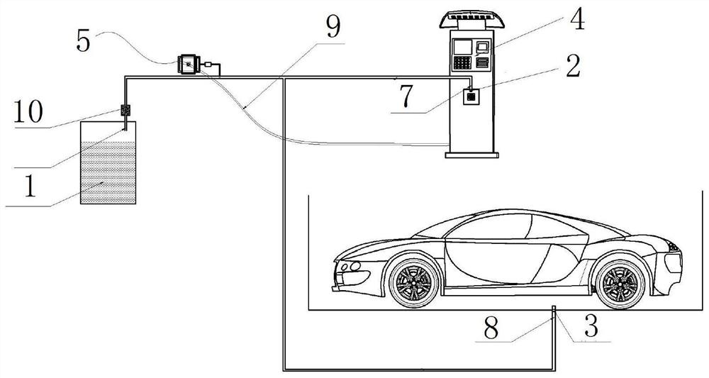
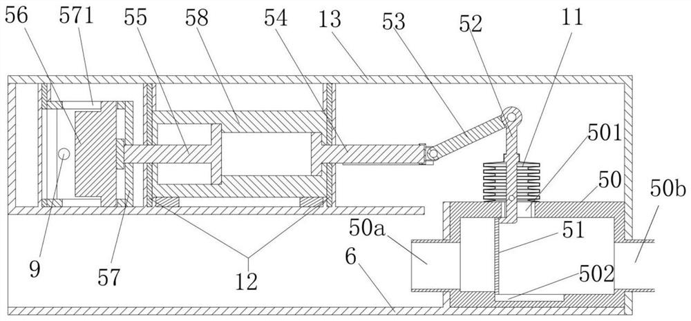
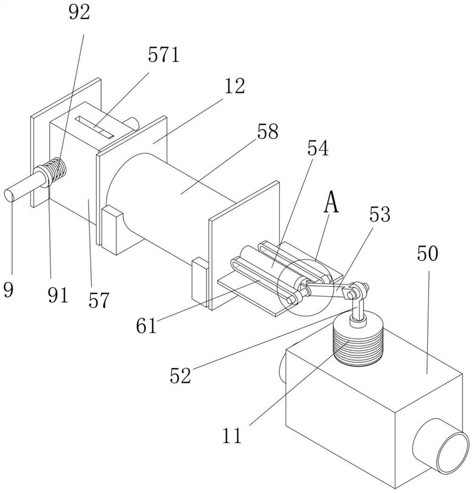
[0022] Such as Figure 1 to Figure 6 As shown, a new energy charging pile that can extinguish fires in time and automatically cut off power includes a tank body 1, a fuse valve 1, a fuse valve 3, a charging pile 4, and a cut-off device 5, the cut-off device 5 is arranged in a fixed box Within 6;

[0023] The cutting device 5 includes a square tube 50, a baffle 51, a rotating member 52, a connecting rod 53, and a piston cylinder 58, the air inlet end 50a of the square tube 50 communicates with the tank 1 through a pipe, and the air outlet end 50b passes through The pipeline is simultaneously connected with the air outlet 7 on the charging pile 4 and the air outlet 2 8 under the car battery. The air outlet 1 7 and the air outlet 2 8 are respectively equippe...


PUM


Abstract

The invention discloses a new energy charging pile capable of timely extinguishing fire and automatically powering off, and relates to the field of new energy, the new energy charging pile comprises atank body, a fusing valve I, a fusing valve II, a charging pile and a cut-off device, and the cut-off device is arranged in a fixed box. The fusing valve is adopted to serve as a fire monitoring device. Different from a sensor, the fusing valve does not need to be connected with a controller, is automatically opened when meeting high temperature, avoids influences caused by faults of a control system, is opened, automatically releases pressure of carbon dioxide in the tank body to spray out fire, drives the baffle to rotate when spraying out high-pressure carbon dioxide. Power is transmittedto the piston cylinder through the rotating part and the connecting rod, then the piston cylinder further lifts acting force and drives the ceramic knife to cut off the power line, the power line is bounced off and separated under the action of the spring, and electric shock hazards caused by untimely power disconnection are avoided. The whole device does not need electric signal control, belongsto passive fire extinguishing and power failure, is not affected by fire due to no electric signal control, and is low in failure rate and high in safety.

Description

Technical field [0001] The invention relates to the field of new energy, in particular to a new energy charging pile that can extinguish fires in time and automatically cut off power. Background technique [0002] Existing new energy vehicle charging piles all have external spear heads. When charging the car, the external spear head is directly inserted into the car charging port. This charging method will generate heat accumulation at the tip of the gun, and heat accumulation inside the battery due to unstable voltage or poor contact. Once the heat accumulates, it will easily cause a fire. [0003] The patent of CN105564264B invented a charging pile with a fire extinguishing monitoring system, but the charging pile is based on a temperature sensor and infrared temperature measuring equipment to detect the fire, and then the fire extinguishing device is activated. The detection device is greatly affected by the temperature measurement position. Information is transmitted through e...

Claims


Application Information

Patent Timeline
Patent Type & Authority Applications(China)
IPC IPC(8): B60L53/30A62C3/16A62C37/11A62C37/20A62C99/00B60L53/31
CPCA62C3/16A62C37/11A62C37/20A62C99/0027B60L53/30B60L53/31Y02T10/70Y02T10/7072Y02T90/12
Inventor 檀生辉陶振吴勇王东朱岳松伍旭东刘恒王凯吴二导孙鸿健姜敏何志维齐红青王铭
Owner 西安电子科技大学芜湖研究院
Why Eureka
Try Eureka