
Speed ​​reduction mechanism and its winding device

A technology of deceleration mechanism and wire winding device, which is applied in the field of coiling and pulling wires, and can solve problems such as hitting and scaring users

Active Publication Date: 2022-07-08
ATEN INT CO
View PDF0 Cites 0 Cited by
  • Summary
  • Abstract
  • Description
  • Claims
  • Application Information

AI Technical Summary

Problems solved by technology

Although this can ensure that the wire is recycled into the reel device, but when the signal wire is reclaimed, when one end of the wire is closer to the reel device, if you do not pay attention, it is easy to cause the user to be hit by one end of the signal wire, or because of recycling If the speed is too fast, one end of the wire will hit the winding device and make a loud noise that will startle the user

Method used


Image

  • Speed ​​reduction mechanism and its winding device
  • Speed ​​reduction mechanism and its winding device
  • Speed ​​reduction mechanism and its winding device

Examples


Embodiment Construction

[0027] Various illustrative embodiments may be described more fully hereinafter with reference to the accompanying drawings, in which some illustrative embodiments are shown. The inventive concepts may, however, be embodied in many different forms and should not be construed as limited to the exemplary embodiments set forth herein. Rather, these illustrative embodiments are provided so that this disclosure will be thorough and complete, and will fully convey the scope of the inventive concept to those skilled in the art. Like numerals indicate corresponding similar elements. The deceleration mechanism and the wire winding device thereof will be described below with various embodiments in conjunction with the drawings, however, the following embodiments are not intended to limit the present invention.

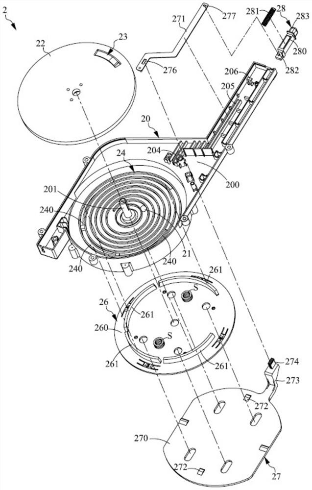
[0028] see figure 2 As shown, it is an exploded schematic diagram of the deceleration mechanism of the present invention. In this embodiment, the deceleration mechanism 2 in...


PUM


Abstract

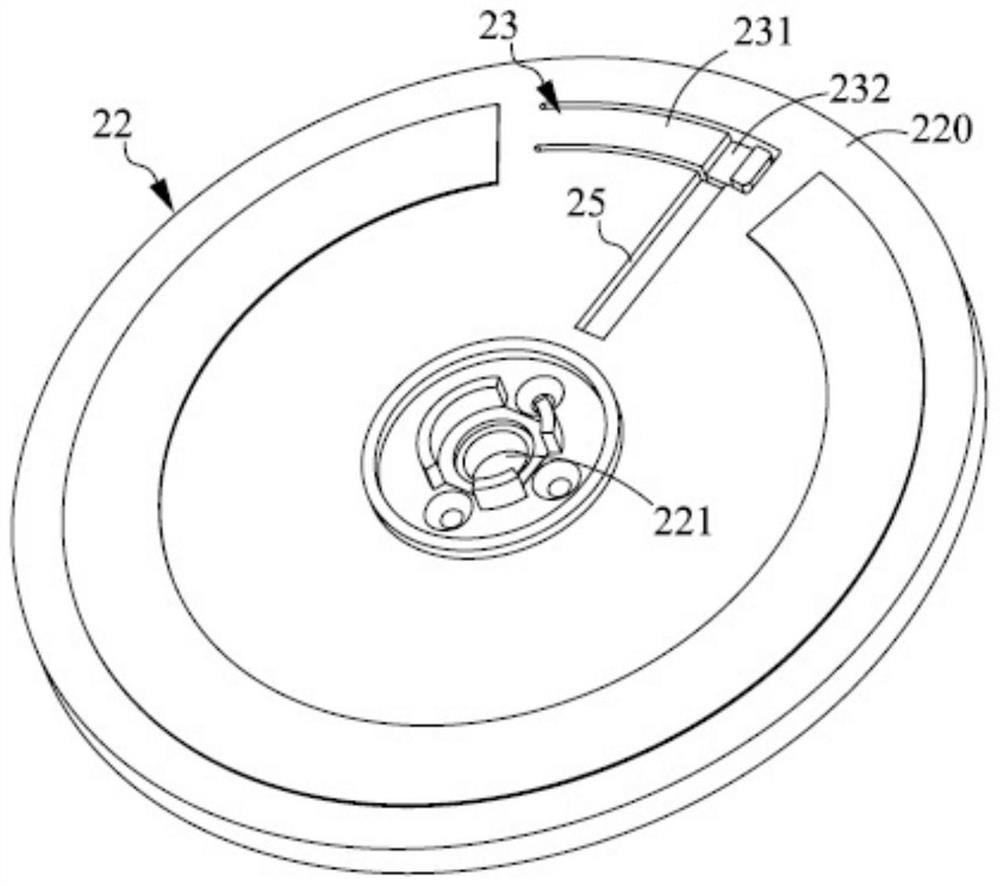
The invention provides a deceleration mechanism comprising a casing, a moving part, a rotating part and a damping part. The movable member is movably arranged on the helical track on the first surface of the casing. The rotating member is rotatably connected to the casing, the rotating member has a second surface opposite to the first surface, and the rotating member includes an actuating part arranged on the second surface and abutting with the moving member, when the rotating member is opposite to the casing When rotating, the actuating part drives the driving member to move in the helical track. The damping part is selectively arranged on the rotating part and corresponds to the deceleration section of the spiral track, wherein when the moving part enters the decelerating section, the damping part presses against the moving part to reduce the rotation speed of the rotating part and the casing. In one embodiment, the deceleration mechanism is combined with the wire winding device to form a wire winding device with a deceleration function, so that the casing can be appropriately decelerated when the end of the wire is approached.

Description

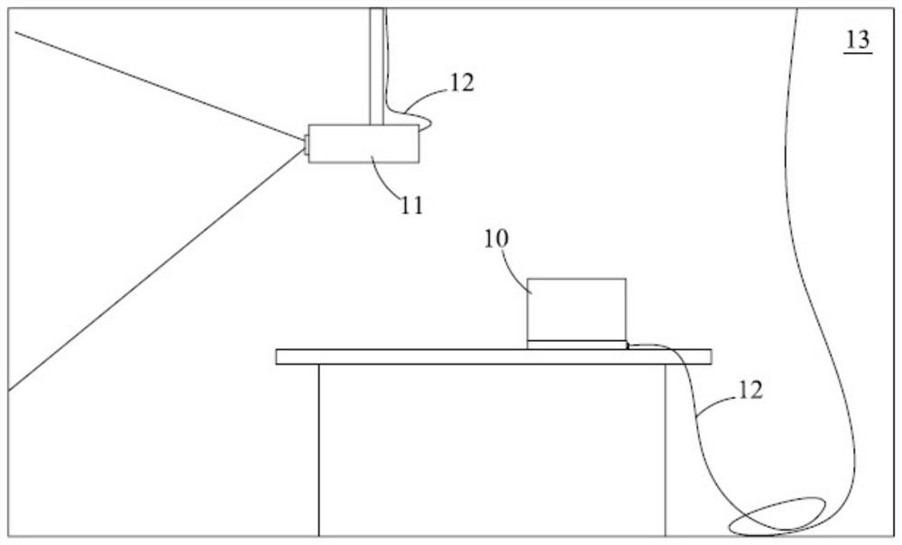
【Technical field】 [0001] The present invention relates to a technology for winding and pulling a wire, in particular to a deceleration mechanism and a wire winding device with control of the winding speed of the wire. 【Background technique】 [0002] see figure 1 As shown, it is a schematic diagram of the relationship between video output and input in a conference room in the prior art. In the prior art, taking the conference room 13 as an example, there are generally multimedia output devices, such as projectors or flat-panel displays, and multimedia input devices, such as computers, DVD players, or portable computers. In this application situation, figure 1 In order to facilitate the connection with the user's portable computer, the signal input end of the projector 11 in the figure uses a signal wire as the connection medium. However, since users in different positions in the conference room can connect to the signal cable, long signal cables must be used. [0003] exi...

Claims


Application Information

Patent Timeline
Patent Type & Authority Patents(China)
IPC IPC(8): B65H75/16B65H75/18B65H75/38B65H75/44
CPCB65H75/16B65H75/18B65H75/38B65H75/4439
Inventor 陈智明
Owner ATEN INT CO
Learn More