
Multidirectional rotary connecting structure based on machine

A technology of rotary connection and connection structure, which is applied in the direction of mechanical equipment, pipes/pipe joints/fittings, pipe supports, etc., which can solve the problem of poor convenience, insufficient fastness of clamp connection bolts and nuts, and inability to realize joint locking and anti-locking of multiple locking structures. Loose and other problems to achieve the effect of improving the fixing effect and improving convenience

Inactive Publication Date: 2020-11-17
游岳
View PDF1 Cites 1 Cited by
  • Summary
  • Abstract
  • Description
  • Claims
  • Application Information

AI Technical Summary

Problems solved by technology

[0007] In order to solve the above-mentioned technical problems, the present invention provides a mechanically based multi-directional rotary connection structure to solve the existing problem that although the existing device can realize multi-directional adjustment, it cannot realize automatic adjustment after adjustment through structural improvement. Locking, and the common locking and anti-loosening of multiple locking structures cannot be realized; moreover, the hoop in the existing device is not fast enough when connecting the bolts and nuts, and two wrenches are needed to adjust during adjustment, which is less convenient The problem

Method used


Image

  • Multidirectional rotary connecting structure based on machine
  • Multidirectional rotary connecting structure based on machine
  • Multidirectional rotary connecting structure based on machine

Examples


Embodiment

[0034] as attached figure 1 to attach Figure 8 Shown:

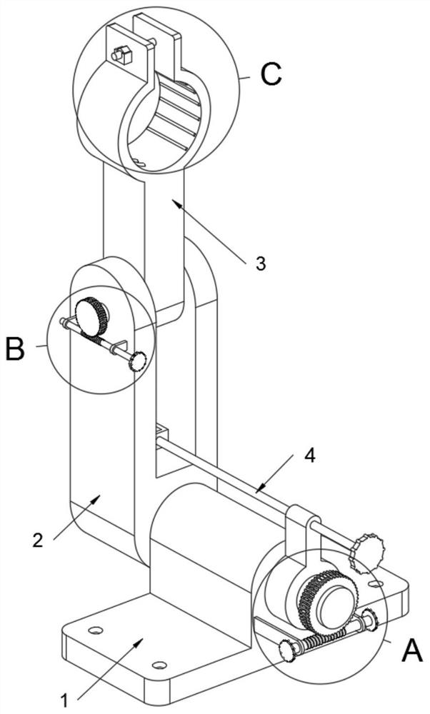
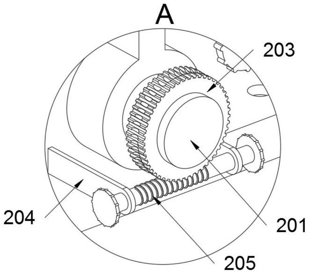
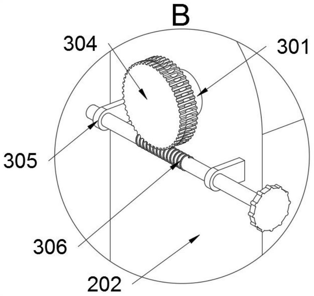
[0035]The present invention provides a multi-directional rotating connection structure based on machinery, including a base 1; a connecting arm structure 2 is connected to the base 1, and a connecting structure 3 is connected to the connecting arm structure 2, and an auxiliary structure 2 is connected to the connecting arm structure 2; Structure 4; refer to eg Figure 5 and Figure 7 , the connection structure 3 includes a nut seat 307 and a nut 308, the nut seat 307 is welded on the clamp 303, and a nut 308 is placed in the nut seat 307, and when the nut 308 is placed in the nut seat 307, the nut 308 is in a position-limiting state , thus improving the convenience when the clamp 303 bolt is locked; refer to as Figure 5 and Figure 7 , the connection structure 3 also includes a fixing hole B30303, and the clamp 303 is provided with a fixing hole B30303; when the nut 308 is placed in the nut seat 307, the threaded h...


PUM


Abstract

The invention provides a multidirectional rotary connecting structure based on a machine, relates to the technical field of connecting structures. The invention aims to solve the problems that automatic locking after adjustment cannot be realized through structural improvement, and combined locking of multiple locking structures cannot be realized; a hoop is not fast enough in connection with a bolt and a nut, and needs to be adjusted by using two wrenches during adjustment; and consequently the convenience is poor. The multidirectional rotary connecting structure based on the machine comprises a base; and the base is connected with a connecting arm structure connected with a connecting structure and an auxiliary structure. A connecting block is welded on a main body seat, and a connectingblock is rotatably connected with the head end of a threaded rod; the connecting seat, the threaded rod and the connecting block jointly form an auxiliary loose-proof structure of the main body seat,so that the auxiliary anti-loosening structure can be used as an adjusting and locking structure except for a regulating rod B.

Description

technical field [0001] The invention belongs to the technical field of connecting structures, and more specifically relates to a mechanically based multi-directional rotating connecting structure. Background technique [0002] Some connecting rods on the mechanical equipment need to be fixed, and the position of the pipeline needs to be adjusted slightly during use. [0003] For example, the application number: CN201610965821.8, a damping rotary connection structure, including a positioning column, a damping ring, a first connecting piece and a second connecting piece. The positioning column is provided with an embedding groove. The damping ring includes a ring body and a limiting part, the limiting part is connected with the ring body, and the ring body is sleeved outside the embedding groove. The first connecting piece is connected with the positioning column. The second connecting piece is provided with an accommodating area, and a limiting groove is provided on the si...

Claims


Application Information

Patent Timeline
IPC IPC(8): F16L3/16
CPCF16L3/16
Inventor 游岳
Owner 游岳
Learn More