Electronic product supporting frame

A technology for electronic products and support frames, applied in the field of support frames, can solve the problems of numerous parts, cumbersome structure, no blocking force, etc., and achieve the effect of simplifying parts, easy to use, and optimizing assembly

Active Publication Date: 2020-11-17
深圳市岸木科技有限公司
View PDF7 Cites 0 Cited by
  • Summary
  • Abstract
  • Description
  • Claims
  • Application Information

AI Technical Summary

Problems solved by technology

Most of the existing supporting equipment for electronic products is mechanical and controlled by gravity. Although it is convenient to use, it also has some disadvantages: due to the different sizes of electronic products, and the large difference in length and width, the traditional clamping The direction is mainly clamping from the side, which cannot adapt to the size and specifications of the electronic product after it is placed horizontally, and when the electronic product moves up and down due to bumps, the firm clamping triangle formed from the side and bottom cannot continue to be maintained, and the side clamping also cannot Unable to form restrictions on up and down movement, no effective blocking force, and unable to meet the needs of horizontally placed mobile phones and horizontal screens
[0005] However, in the actual production of this structure, there are some problems including many parts, complex assembly, and cumbersome structure. In today's increasingly pursuit of efficiency and cost, it needs to be further streamlined and optimized.

Method used


Image

  • Electronic product supporting frame
  • Electronic product supporting frame
  • Electronic product supporting frame

Examples


Embodiment 1

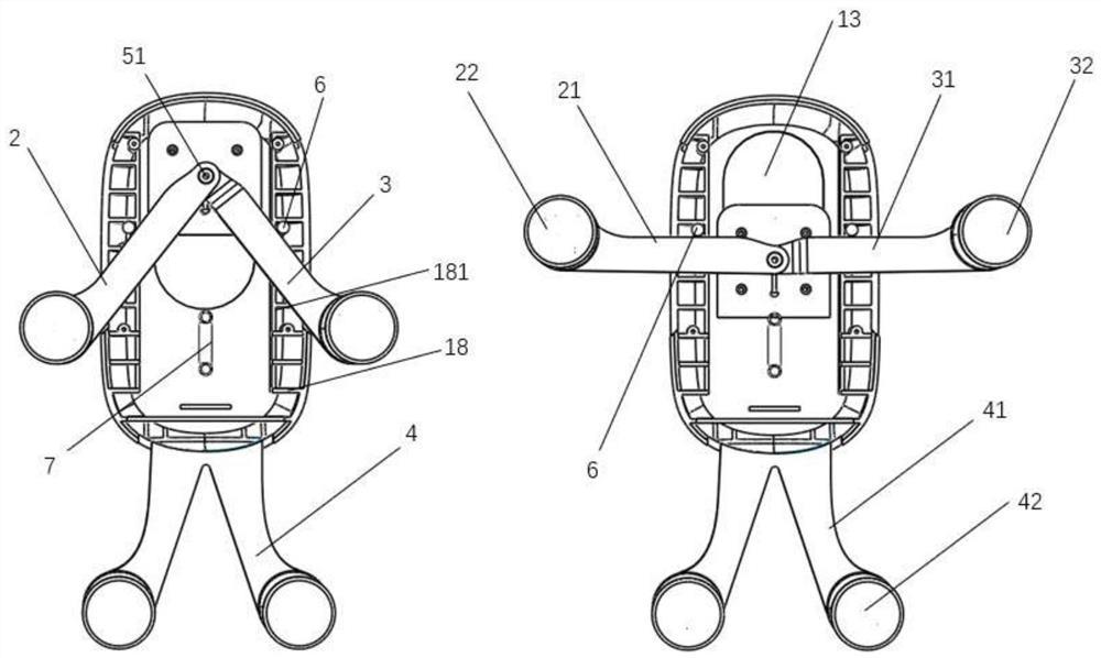
[0067] see Figure 1-3 , a support frame for electronic products, comprising: a housing 1, the housing 1 includes a front housing 11 and a rear housing 12, the rear housing 12 is provided with an opening 13, and the front and rear housings (11, 12) are connected Then the cavity 14 is formed. The cavity 14 is movable and partially accommodates the inner ends of the left and right clamping parts ( 2 , 3 ) for clamping the electronic product from the top and the side, and the inner end of the driving rod 51 .

[0068] The front housing 11 is in the shape of a cover plate, and the front surface is set as a concave surface, so as to facilitate the external attachment of the decorative shell 16 to cover the mounting structures on the surface of the front housing 11 such as threaded holes and screw ends. The rear housing 12 is in the shape of a concave cavity to form a receiving space for installing linkage components.

[0069] The front and rear housings (11, 12) are fastened and ...

Embodiment 2

[0090] The structure and principle of this embodiment are basically the same as those of Embodiment 1, the main difference lies in: the sliding part and the sliding structure.

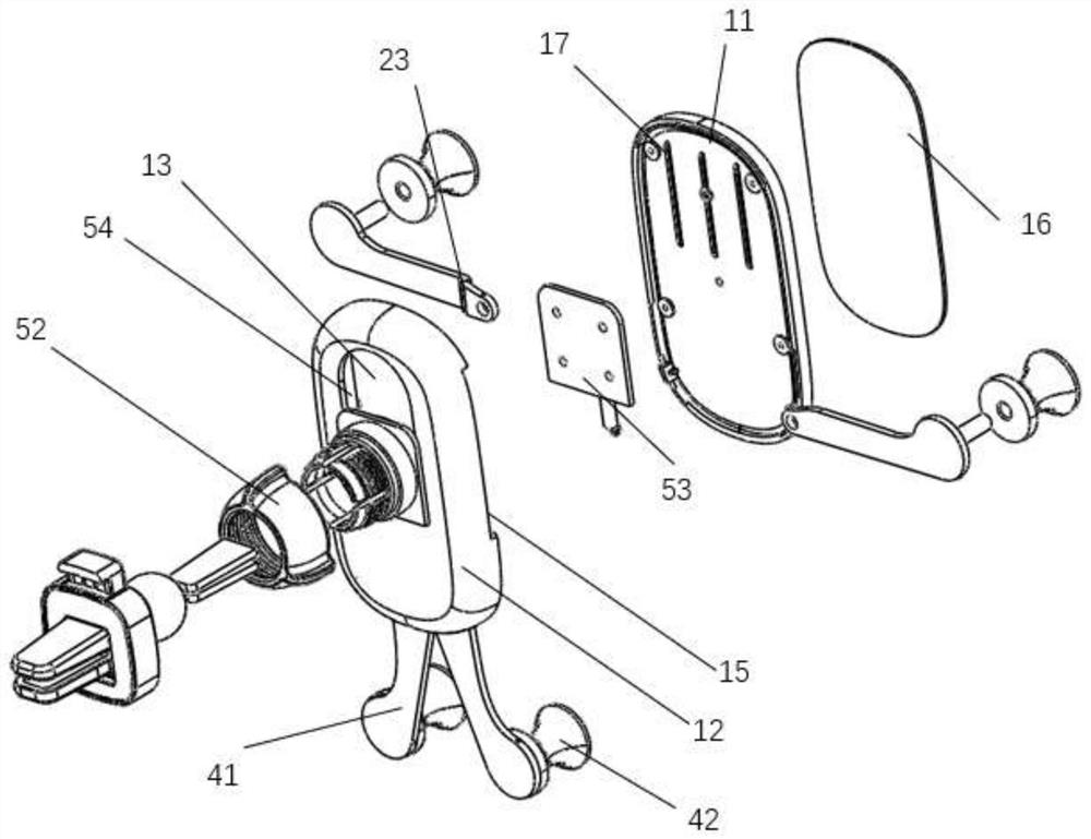
[0091] see Figure 4-7 , the fixing assembly 5 is connected with the casing 1 through a sliding structure to realize the above-mentioned activities. The sliding structure includes a slider and a slideway, and the slider can slide along the slideway.

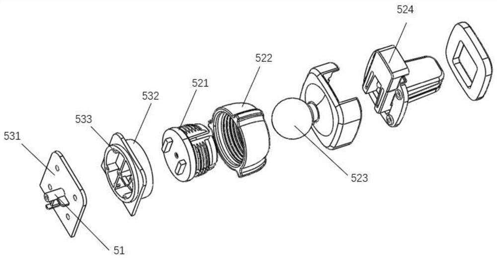
[0092] Specifically, the fixing assembly 5 includes a fixing part 52 and a sliding part 53, the driving rod 51 is arranged on the sliding part 53, and the fixing part 52 is adapted to be connected with the carrier. The sliding portion 53 includes a third sliding portion 535 provided with a drive rod 51, the edge of the third sliding portion 535 is formed with a projection 5351 that can slide on the mouth edge 54 of the opening 53, the projection 5351 is a slider, and the opening 13 The mouth edge 54 forms a slideway, and the opening 13 is also provided ...

Embodiment 3

[0096] The structure and principle of this embodiment are basically the same as those of Embodiment 1, the main difference lies in: the sliding part and the sliding structure.

[0097] see Figure 8 , the fixing assembly 5 is connected with the casing 1 through a sliding structure to realize the above-mentioned activities. The sliding structure includes a slider and a slideway, and the slider can slide along the slideway.

[0098]Specifically, the fixing assembly 5 includes a fixing part 52 and a sliding part 53, the driving rod 51 is arranged on the sliding part 53, and the fixing part 52 is adapted to be connected with the carrier. The sliding part 53 includes a fourth sliding part 537 provided with a drive rod 51. The two sides of the mouth edge 54 of the opening 13 are respectively provided with slide rails 5371. The slide rails 5371 are strip-shaped protrusions formed on the inner side of the mouth edge 54. The gap between the riser and the mouth edge 54 forms a slidewa...


PUM


Abstract

The invention provides an electronic product supporting frame which comprises a shell, a fixing assembly, a bottom supporting part, a left clamping part and a right clamping part. An opening is formedin the rear portion of the shell. The fixing assembly is movably connected with the shell through the opening. The bottom supporting part is suitable for supporting an electronic product from the bottom of the electronic product. The left clamping part and the right clamping part are movably connected with the shell correspondingly, so that the left clamping part and the right clamping part can rotate. The fixing assembly comprises a driving rod which can extend into the opening and is connected with the left clamping part and the right clamping part, and the shell moves to drive the drivingrod to drive the left clamping part and the right clamping part to clamp the electronic product from the upper portion and / or the side portion of the electronic product. Due to the fact that the driving rod is arranged on the fixing assembly and serves as a drive to directly drive the left clamping part and the right clamping part to clamp the electronic product, parts are simplified, assembly isoptimized, the requirement for clamping the electronic product in all directions (the transverse direction and the vertical direction) is met, and use is more convenient.

Description

technical field [0001] The invention relates to the field of support frames, in particular to a support frame for electronic products. Background technique [0002] With the popularization of electronic products, electronic products are gradually becoming an indispensable necessity in people's life. Most of the existing supporting equipment for electronic products is mechanical and controlled by gravity. Although it is convenient to use, it also has some disadvantages: due to the different sizes of electronic products, and the large difference in length and width, the traditional clamping The direction is mainly clamping from the side, which cannot adapt to the size and specifications of the electronic product after it is placed horizontally, and when the electronic product moves up and down due to bumps, the firm clamping triangle formed from the side and bottom cannot continue to be maintained, and the side clamping also cannot There is no restriction on the up and down m...

Claims


Application Information

Patent Timeline
Patent Type & Authority Applications(China)
IPC IPC(8): F16M11/04F16M11/20
CPCF16M11/04F16M11/041F16M11/2078
Inventor 石磊
Owner 深圳市岸木科技有限公司
Why Eureka
Try Eureka