Positioning mechanism for improving welding efficiency for exhaust manifold and flange

A technology of flange welding and exhaust manifold, which is applied in the field of positioning mechanism to improve the efficiency of exhaust manifold and flange welding, and can solve the problems of long length, difficult exhaust manifold fixing, complex shape of exhaust manifold, etc. , to achieve the effect of improving welding efficiency and facilitating quick alignment

Inactive Publication Date: 2017-12-01
CHENGDU LINGCHUAN SPECIAL IND
View PDF5 Cites 2 Cited by
  • Summary
  • Abstract
  • Description
  • Claims
  • Application Information

AI Technical Summary

Problems solved by technology

[0004] In order to facilitate the assembly and connection of the exhaust manifold, it is necessary to clamp the exhaust manifold and the flange surface during processing to facilitate the welding of the exhaust manifold and the flange. At present, due to the shape of the exhaust manifold It is complicat

Method used


Image

  • Positioning mechanism for improving welding efficiency for exhaust manifold and flange
  • Positioning mechanism for improving welding efficiency for exhaust manifold and flange
  • Positioning mechanism for improving welding efficiency for exhaust manifold and flange

Examples


Example Embodiment

[0025] Example

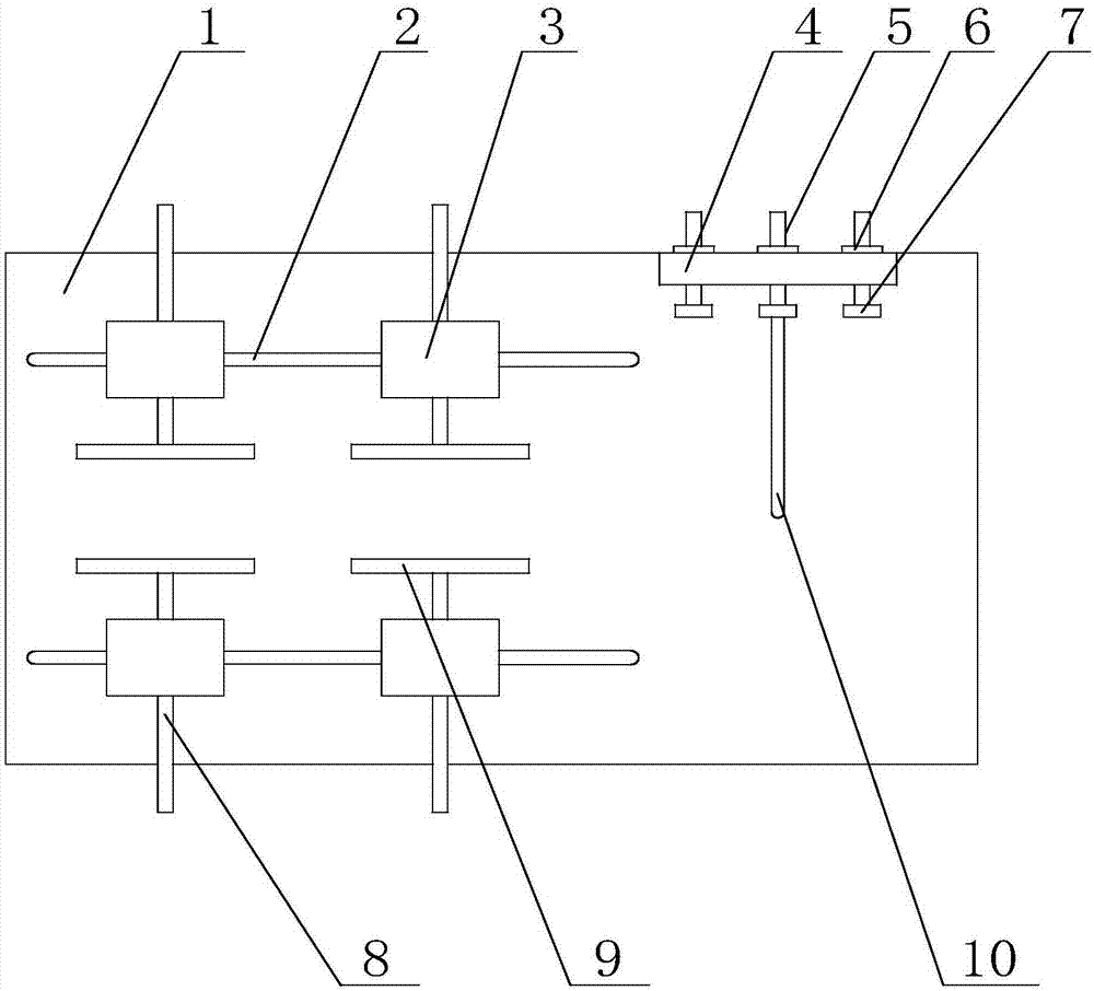
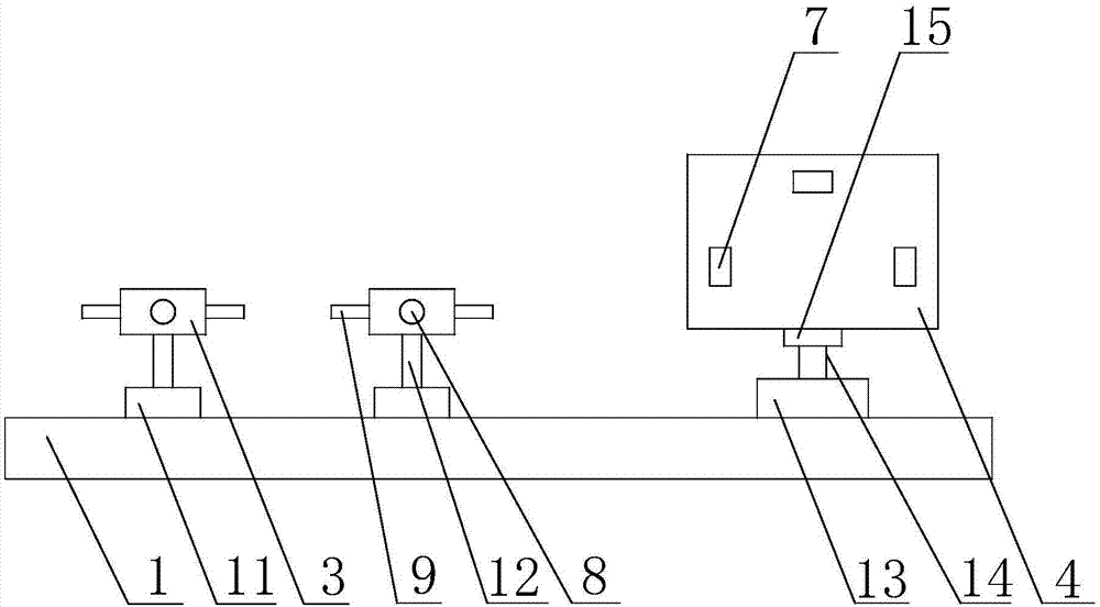
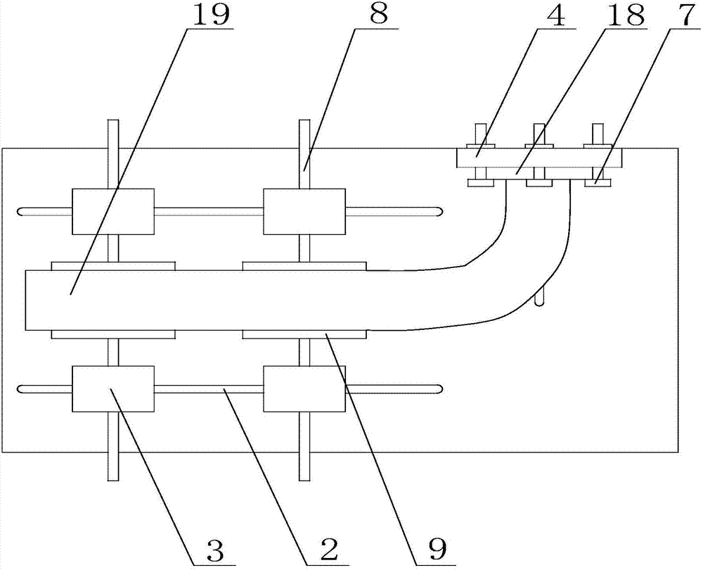
[0026] like Figure 1 to Figure 4 As shown, the positioning mechanism for improving the welding efficiency of the exhaust manifold and the flange of the present invention includes a base 1, the base 1 is a rectangular structure, and the top of the base 1 is provided with two first chute 2, the first chute 2 Located on both sides of the axis of the base 1, two first drive mechanisms 11 are arranged in the first chute 2, the first drive mechanism 11 is preferably a hydraulic cylinder, which is convenient to control and works stably. The first drive mechanism 11 Both can move in the first chute 2 to adjust the distance between the two first drive mechanisms 11, the first drive mechanism 11 includes a first drive shaft 12, the top of the first drive shaft 12 is provided with a fixed block 3. The movable rod 8 is provided on the fixed block 3, and the movable rod 8 is horizontally connected with the fixed block 3 through threads, and the movable rod 8 is rotated, ...


PUM


Abstract

The invention discloses a positioning mechanism for improving the welding efficiency for an exhaust manifold and a flange. The positioning mechanism for improving the welding efficiency for the exhaust manifold and the flange comprises a base. A plurality of first driving mechanisms are arranged at the top of the base, and the first driving mechanisms can move on the base. Each first driving mechanism comprises a first driving shaft, wherein a clamping plate used for clamping the exhaust manifold is arranged at the top of the first driving shaft. A second driving mechanism is further arranged at the top of the base and can move on the base. The second driving mechanism comprises a second driving shaft, wherein a side table is arranged at the top of the second driving shaft, and the side table can rotate around the second driving shaft; and limiting plates used for clamping the flange are arranged on the side table. By adoption of the poisoning mechanism for improving the welding efficiency for the exhaust manifold and the flange, exhaust manifolds in different shapes can be clamped, and the weld portions of the flange and the exhaust manifold can be aligned conveniently.

Description

technical field [0001] The invention relates to a processing tool for automobile parts, in particular to a positioning mechanism for improving the welding efficiency of exhaust manifolds and flanges. Background technique [0002] The exhaust manifold is connected to the cylinder block of the engine, and gathers the exhaust of each cylinder into the exhaust manifold, with divergent pipelines. The main requirements for it are to minimize exhaust resistance and avoid mutual interference between cylinders. When the exhaust is too concentrated, there will be mutual interference between the cylinders, that is, when a certain cylinder exhausts, it happens to encounter the undischarged exhaust gas from other cylinders. In this way, the resistance of the exhaust will be increased, thereby reducing the output power of the engine. The solution is to separate the exhaust of each cylinder as much as possible, one branch for each cylinder, or one branch for two cylinders, and make each ...

Claims


Application Information

Patent Timeline
IPC IPC(8): B23K37/04
CPCB23K37/0443B23K2101/006
Inventor 梁静杨军
Owner CHENGDU LINGCHUAN SPECIAL IND
Why Eureka
Try Eureka