Welding method of exhaust manifold and connection component

A technology for exhaust manifolds and connecting parts, which is applied in the field of automotive parts processing tools, can solve the problems of long length, difficult exhaust manifold fixing, complex shape of exhaust manifold, etc., and achieve the effect of easy and quick alignment

Inactive Publication Date: 2018-01-05
CHENGDU LINGCHUAN SPECIAL IND
View PDF4 Cites 2 Cited by
  • Summary
  • Abstract
  • Description
  • Claims
  • Application Information

AI Technical Summary

Problems solved by technology

[0004] In order to facilitate the assembly and connection of the exhaust manifold, it is necessary to clamp the exhaust manifold and the flange surface during processing to facilitate the welding of the exhaust manifold and the flange. At present, due to the shape of the exhaust manifold It is complicated and long in length, and it is difficult for traditional fixtures to locate and fix such complex-shaped exhaust manifolds. Especially when processing the large surface of exhaust manifolds, it is difficult for the clamping devices attached to traditional fixtures to The exhaust manifold is fully fixed

Method used


Image

  • Welding method of exhaust manifold and connection component
  • Welding method of exhaust manifold and connection component
  • Welding method of exhaust manifold and connection component

Examples


Embodiment

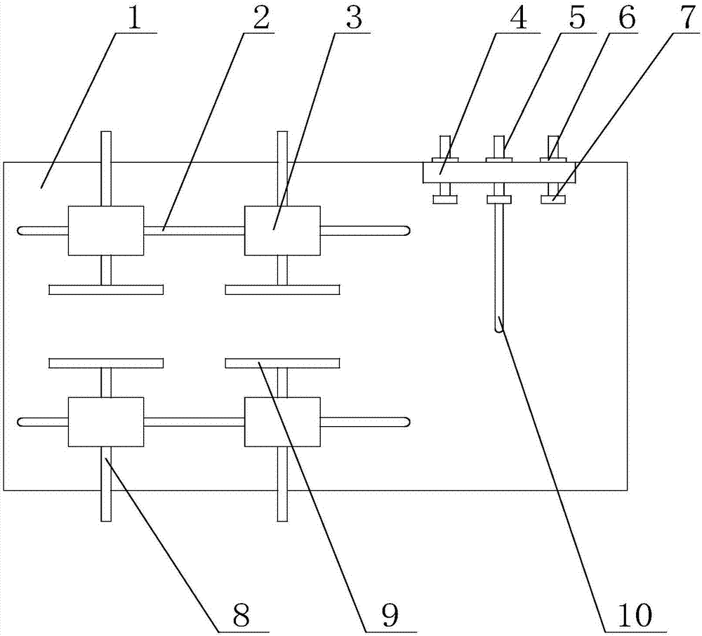
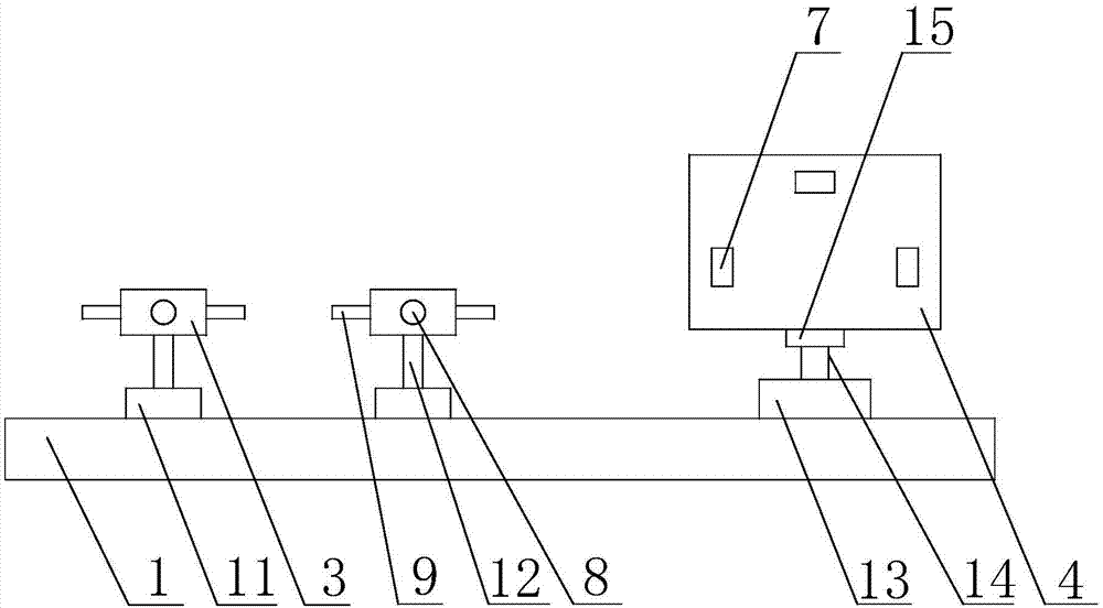
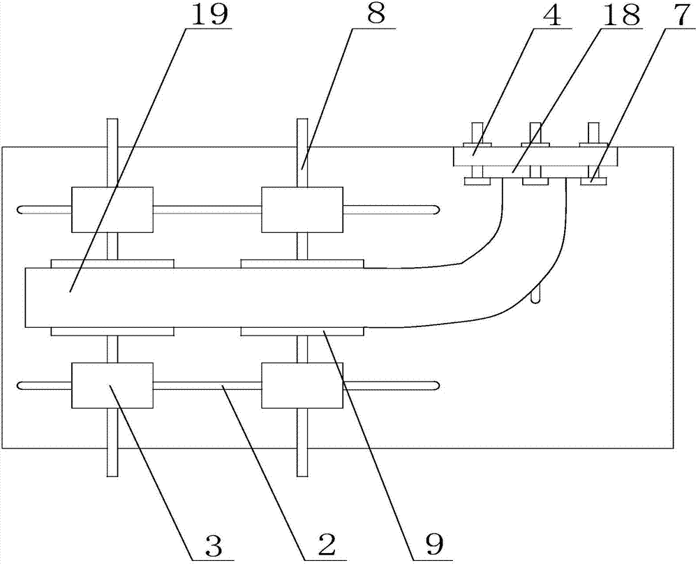
[0027] Such as Figure 1 to Figure 4 As shown, the present invention is based on the welding method of the exhaust manifold and the connecting parts, including the following steps: first place the base 1 horizontally, place the flange 18 to be welded on the side of the side table 4, and use the limit plate 7 to clamp At the edge of the flange 18, the flange 18 is fixed on the side platform 4 through the fixing ring 6, and then the side of the exhaust manifold 19 to be welded is placed between the fixing blocks 3, and the second chute 10 moves along the second The second driving mechanism 13 adjusts the height of the side table 4 at the same time, so that the welding place between the flange 18 and the exhaust manifold 19 is at the same height, and then the flange 18 is rotated around the second driving shaft 14 to ensure the welding of the flange 18 The surface is in contact with the welding surface of the exhaust manifold 19, and the exhaust manifold 19 is kept stationary, an...


PUM


Abstract

The invention discloses a welding method of an exhaust manifold and a connection component. The welding method of the exhaust manifold and the connection component comprises the following steps that firstly, a base is horizontally placed, a flange to be welded is placed on the side face of a side platform, the edge of the flange is clamped through limiting plates, and the flange is fixed to the side platform through fixing rings; secondly, one side of the exhaust manifold to be welded is placed between fixing blocks, a second drive mechanism is moved along a second sliding groove, the height of the side platform is adjusted at the same time, and the welding portion of the flange and the welding portion of the exhaust manifold are made to be located at the same height; and thirdly, the flange is rotated around a second drive shaft, it is guaranteed that the welding face of the flange is in contact with the welding face of the exhaust manifold, the exhaust manifold is kept fixed, movablerods are sequentially adjusted to enable clamp plates to fix the exhaust manifold, when the exhaust manifold is fixed, the heights of the clamp plates are adjusted through first drive mechanisms, meanwhile the intervals between the clamp plates are adjusted through first sliding grooves, the clamping force on the exhaust manifold is increased, and when the exhaust manifold is well fixed, the exhaust manifold and the flange are welded.

Description

technical field [0001] The invention relates to a processing tool for automobile parts, in particular to a welding method based on an exhaust manifold and connecting parts. Background technique [0002] The exhaust manifold is connected to the cylinder block of the engine, and gathers the exhaust of each cylinder into the exhaust manifold, with divergent pipelines. The main requirements for it are to minimize exhaust resistance and avoid mutual interference between cylinders. When the exhaust is too concentrated, there will be mutual interference between the cylinders, that is, when a certain cylinder exhausts, it happens to encounter the undischarged exhaust gas from other cylinders. In this way, the resistance of the exhaust will be increased, thereby reducing the output power of the engine. The solution is to separate the exhaust of each cylinder as much as possible, one branch for each cylinder, or one branch for two cylinders, and make each branch as long as possible ...

Claims


Application Information

Patent Timeline
Patent Type & Authority Applications(China)
IPC IPC(8): B23K37/00B23K31/02B23K37/04
Inventor 袁春志汪庭文张军
Owner CHENGDU LINGCHUAN SPECIAL IND
Why Eureka
Try Eureka