Hydraulic structure for controlling and clamping drill bit of drilling machine
What is Al technical title?
Al technical title is built by PatSnap Al team. It summarizes the technical point description of the patent document.
A drill bit and hydraulic technology, applied in the direction of engine seals, mechanical equipment, engine components, etc., can solve the problems of not holding the drill bit too much, affecting the stability of the hydraulic cylinder, poor maintenance conditions, etc., achieving light weight, structure Simple, the effect of avoiding quality accidents
Inactive Publication Date: 2017-05-31
泸州长江液压密封件有限公司
View PDF7 Cites 2 Cited by
Summary
Abstract
Description
Claims
Application Information
AI Technical Summary
This helps you quickly interpret patents by identifying the three key elements:
Problems solved by technology
Method used
Benefits of technology
Problems solved by technology
[0003] The technical problem to be solved by the present invention is that when the hydraulic cylinder clamps the drill bit of the drilling rig, the pressure of the clamping drill bit needs to be kept constant, and the pressure of clamping the drill bit can neither be too large nor too small, and the hydraulic cylinder wo
Method used
Image
Click on the blue label to locate the original text in one second.
Reading with bidirectional positioning of images and text.
Examples
Embodiment
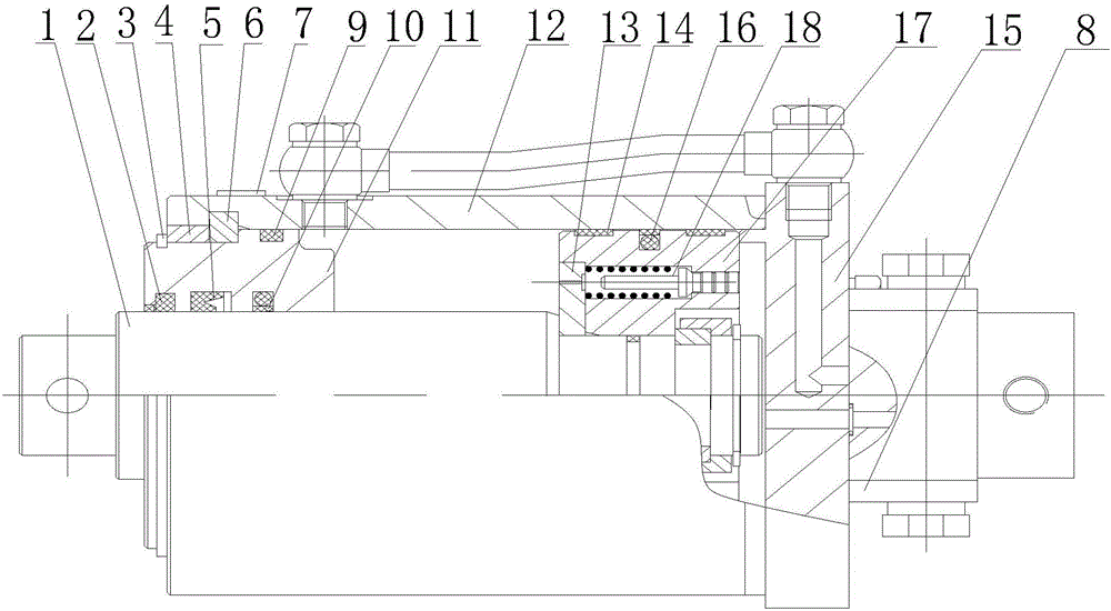
[0024] Such as figure 1 As shown, the present invention is a kind of hydraulic structure that is used for controlling the clamping drilling rig bit, comprises cylinder barrel 12, piston rod 1, piston 17 and cylinder bottom 15, and described piston rod 1 is arranged in the cylinder barrel 12, and piston rod 1 and The piston 17 is connected, and the cylinder 12 and the cylinder bottom 15 are connected by welding. The cylinder 12 and the cylinder bottom 15 form a rodless cavity. Compared with the traditional rod-type hydraulic cylinder, this method can not only Reduce the size and space required by screws and nuts, make it simple in structure, small in size and light in weight, and can also solve the aging of the seal at the end of the cylinder bottom 15, or the leakage of the cylinder bottom 15 caused by some other reasons; the outer wall of the cylinder bottom 15 is equipped with a superimposed liquid control check valve 8, the superimposed hydraulic control check valve 8 is a ...
PUM
Abstract
The invention discloses a hydraulic structure for controlling and clamping a drill bit of a drilling machine. The hydraulic structure comprises a cylinder, a cylinder bottom, a piston and a piston rod, wherein the cylinder is connected with the cylinder bottom in a welding mode to form a rodless cavity. Compared with a pull rod type hydraulic cylinder, the hydraulic structure not only has the advantages of being small in space necessary for screws and screw nuts, simple in structure, small in size, light in weight and the like, but also is capable of solving the problem of cylinder bottom leakage caused by aging of sealing parts at the cylinder bottom or other reasons; as an overlapped hydraulic control one-way valve is arranged on the outer wall of the cylinder bottom, pressure can be maintained when the drill bit is clamped by using the hydraulic cylinder; the piston is provided with a pressure control valve, so that the piston rod can be controlled to move, and furthermore the clamping force of the hydraulic cylinder for clamping a cutter can be controlled; the hydraulic cylinder works frequently, generally works in outdoor working environments, and repairing and maintenance conditions are poor, so that the stability of a moveable hydraulic cylinder needs to be improved; as a guide sleeve is made of high-strength cast iron, quality accidents can be avoided.
Description
technical field [0001] The invention relates to a mechanical transmission mechanism, in particular to a hydraulic structure for controlling and clamping a drill bit of a drilling machine. Background technique [0002] Hydraulic transmission has many outstanding advantages, so it is widely used, such as plastic processing machinery, pressure machinery, machine tools, etc. for general industrial use; engineering machinery, construction machinery, agricultural machinery, automobiles, etc. in walking machinery; Metallurgical machinery, hoisting devices, roll adjustment devices, etc.; flood control gates and dam devices, river bed lifting devices, bridge control mechanisms, etc. for civil and water conservancy projects; turbine speed control devices for power plants, nuclear power plants, etc.; deck lifting machinery for ships (Winch), bow door, bulkhead valve, stern propeller, etc.; giant antenna control device for special technology, measuring buoy, lifting and rotating stage, ...
Claims
Application Information
Patent Timeline
Application Date:The date an application was filed.
Publication Date:The date a patent or application was officially published.
First Publication Date:The earliest publication date of a patent with the same application number.
Issue Date:Publication date of the patent grant document.
PCT Entry Date:The Entry date of PCT National Phase.
Estimated Expiry Date:The statutory expiry date of a patent right according to the Patent Law, and it is the longest term of protection that the patent right can achieve without the termination of the patent right due to other reasons(Term extension factor has been taken into account ).
Invalid Date:Actual expiry date is based on effective date or publication date of legal transaction data of invalid patent.