Optical imaging lens matched with liquid lens

An optical imaging lens and liquid lens technology, applied in the lens field, can solve problems such as resolution, depth of field, magnification, relative illuminance limitation, light far not reachable, etc., to achieve high resolution, high relative illuminance, The effect of high yield rate in mass production

Pending Publication Date: 2020-11-17
XIAMEN LEADING OPTICS
View PDF0 Cites 0 Cited by
  • Summary
  • Abstract
  • Description
  • Claims
  • Application Information

AI Technical Summary

Problems solved by technology

[0003] However, there are still many deficiencies in the current optical imaging lenses with liquid lenses for iris recognition on the market, such as the light transmission is far from the ideal light transmission value required by the application; the relative illuminance is limited by the liquid lens, and the relative illuminance is p

Method used


Image

  • Optical imaging lens matched with liquid lens
  • Optical imaging lens matched with liquid lens
  • Optical imaging lens matched with liquid lens

Examples


Embodiment 1

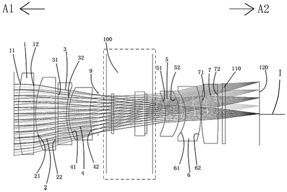
[0077] Such as figure 1 As shown, an optical imaging lens with a liquid lens includes a first lens 1, a second lens 2, a third lens 3, a fourth lens 4, and a diaphragm in sequence along an optical axis I from the object side A1 to the image side A2 9. The liquid lens 100, the fifth lens 5, the sixth lens 6, the seventh lens 7, the protective glass 110 and the imaging surface 120; the first lens 1 to the seventh lens 7 each include a lens facing the object side A1 and allowing the imaging light to pass through The object side and an image side facing the image side A2 through which the imaging light passes.

[0078] The first lens 1 has a positive refractive power, the object side 11 of the first lens 1 is a convex surface, and the image side 12 of the first lens 1 is a convex surface. Of course, in other embodiments, the image side 12 of the first lens 1 can also be is concave or flat.

[0079] The second lens 2 has a positive refractive power, the object side 21 of the seco...

Embodiment 2

[0093] Such as Figure 7 As shown, an optical imaging lens with a liquid lens includes a first lens 1, a second lens 2, a third lens 3, a fourth lens 4, and a diaphragm in sequence along an optical axis I from the object side A1 to the image side A2 9. The liquid lens 100, the fifth lens 5, the eighth lens 8, the sixth lens 6, the seventh lens 7, the protective glass 110 and the imaging surface 120; the first lens 1 to the eighth lens 8 each include a lens facing the object side A1 And an object side through which the imaging light passes and an image side facing the image side A2 through which the imaging light passes.

[0094] The first lens 1 has a positive refractive power, the object side 11 of the first lens 1 is a convex surface, and the image side 12 of the first lens 1 is a concave surface. Of course, in other embodiments, the image side 12 of the first lens 1 can also be is convex or planar.

[0095] The second lens 2 has a positive refractive power, the object sid...

Embodiment 3

[0113] Such as Figure 13 As shown, the concave-convex surface shape and refractive index of each lens in this embodiment and the second embodiment are the same, and only the optical parameters such as the radius of curvature of the lens surface and the thickness of the lens are different. In addition, in this specific embodiment, the second lens 2 and the third lens 3 are glued together, and the third lens 3 and the fourth lens 4 are glued together.

[0114] The detailed optical data of this specific embodiment are shown in Table 3-1.

[0115] Detailed optical data of the third embodiment of table 3-1

[0116]

[0117]

[0118] Please refer to Table 6 for the values ​​of the relevant conditional expressions in this specific embodiment.

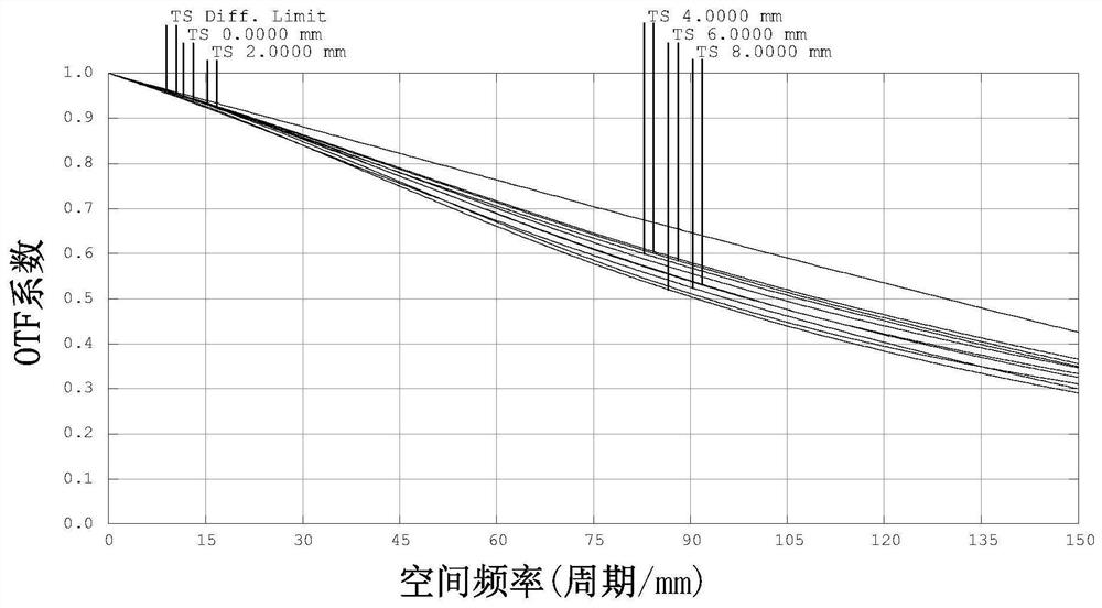
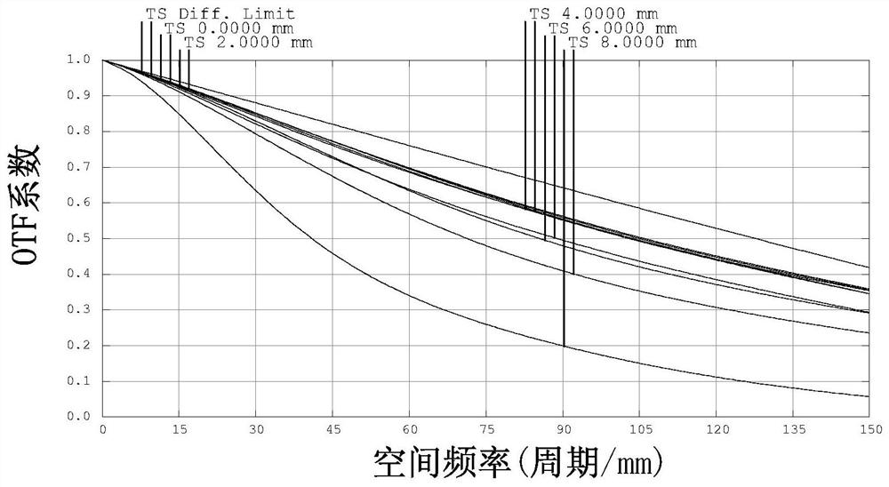
[0119] The MTF transfer function curve diagram of the different working object distances of this specific embodiment is detailed in Figure 14 , 15 and 16, it can be seen that the range of working object distance is wide, and the re...


PUM


Abstract

The invention relates to the technical field of lenses. The invention discloses an optical imaging lens matched with a liquid lens. The optical imaging lens sequentially comprises a first lens to a fourth lens, a diaphragm, a liquid lens, a fifth lens to a seventh lens from an object side to an image side along an optical axis, the first lens and the second lens both have positive refractive indexes, the object side surface is a convex surface, the third lens has a negative refractive index, and the image side surface is a concave surface. The fourth lens is a convex plane or convex-concave lens with a positive refractive index, the fifth lens has a negative refractive index, the object side surface of the fifth lens is a concave surface or a plane, the sixth lens is a concave-convex lenswith a negative refractive index, and the seventh lens has a positive refractive index, and the object side surface of the seventh lens is a convex surface. The optical imaging lens has the advantagesof considering parameters such as resolution, depth of field, magnification and the like, and being wide in working object distance range, high in resolution, good in imaging quality, large in lighttransmission and high in production yield.

Description

technical field [0001] The invention belongs to the technical field of lenses, and in particular relates to an optical imaging lens matched with a liquid lens. Background technique [0002] With the continuous advancement of science and technology and the continuous development of society, optical imaging lenses have also developed rapidly in recent years. Optical imaging lenses are widely used in smart phones, tablet computers, video conferencing, vehicle monitoring, security monitoring, machine vision Systems and other fields, therefore, the requirements for optical imaging lenses are getting higher and higher. [0003] However, there are still many deficiencies in the current optical imaging lenses with liquid lenses for iris recognition on the market, such as the light transmission is far from the ideal light transmission value required by the application; the relative illuminance is limited by the liquid lens, and the relative illuminance is poor; Taking into account p...

Claims


Application Information

Patent Timeline
IPC IPC(8): G02B13/00G02B13/14G06K9/00
CPCG02B13/0055G02B13/0075G02B13/006G02B13/008G02B13/14G06V40/19
Inventor 郑毅黄翔邦李可
Owner XIAMEN LEADING OPTICS
Why Eureka
Try Eureka