Optical system capable of performing grouping focusing, imaging device and lens

An optical system and light technology, applied in the optical field, can solve the problems of reduced imaging quality, reduced imaging quality, and optical lenses cannot meet the requirements of machine vision recognition for lenses, and achieve high resolution, wide working distance, and low distortion. Effect

Inactive Publication Date: 2019-04-23
FUJIAN INST OF RES ON THE STRUCTURE OF MATTER CHINESE ACAD OF SCI
View PDF5 Cites 2 Cited by
  • Summary
  • Abstract
  • Description
  • Claims
  • Application Information

AI Technical Summary

Problems solved by technology

[0004] However, although the above two lenses can image up to 5 million pixels at the optimal working distance, when the working distance deviates from the optimal position, the imaging quality will be greatly reduced. serious
[0005] Existing optical lenses cannot meet the requirements of machine vision recognition for lenses

Method used


Image

  • Optical system capable of performing grouping focusing, imaging device and lens
  • Optical system capable of performing grouping focusing, imaging device and lens
  • Optical system capable of performing grouping focusing, imaging device and lens

Examples


Embodiment 1

[0074] Embodiment 1 Group focusing optical system

[0075] In this embodiment 1, parameter conditions: f=35mm, f A =40.2mm, f B =107.6mm, ΔL=9.7mm, TTHI=40.3mm.

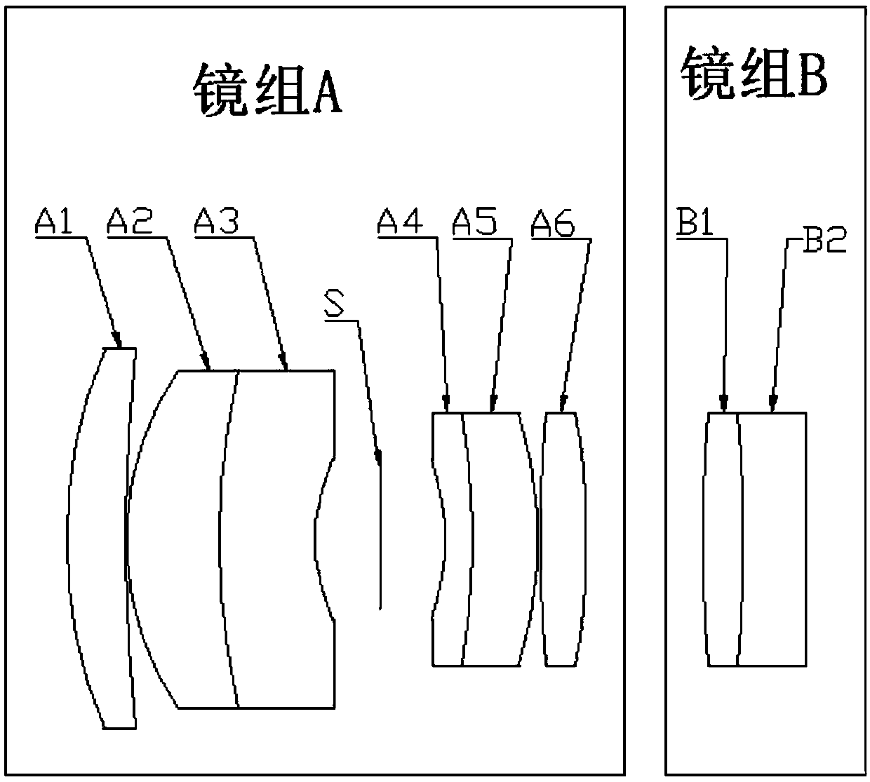
[0076] see figure 1 , in this embodiment 1, the optical system for group focusing includes:

[0077] The first lens group A, meniscus positive lens A1, meniscus positive lens A2, meniscus negative lens A3, variable diaphragm S, meniscus negative lens A4, Meniscus positive lens A5 and biconvex positive lens A6. Wherein the meniscus positive lens A2 and the meniscus negative lens A3 are glued together. The meniscus negative lens A4 and the meniscus positive lens A5 are glued together.

[0078] The second lens group B is a biconvex positive lens B1 and a meniscus negative lens B2 arranged in sequence from the object side to the image side along the incident direction of the light. The cemented surface of the negative lens B2 faces the object side.

[0079] In the present embodiment 1, the technical indicators ac...

Embodiment 2

[0099] Embodiment 2 Group focusing optical system

[0100] In this embodiment 2, parameter condition: f=35mm, f A =40.2mm, f B =110.6mm, ΔL=9.6mm, TTHI=40.1mm.

[0101] see Figure 8 , in this embodiment 2, the optical system for group focusing includes:

[0102] The first lens group A is arranged in sequence along the light incident direction, meniscus positive lens A1, meniscus positive lens A2, meniscus negative lens A3, variable diaphragm S, meniscus negative lens A4, meniscus positive lens A5 And meniscus positive lens A6. Wherein the meniscus negative lens A4 and the meniscus positive lens A5 are glued together.

[0103] The second lens group B is provided with a biconvex positive lens B1 and a biconcave negative lens B2, and the cemented surface of the biconvex positive lens B1 and the meniscus negative lens B2 is cemented, and the cemented surface of the meniscus negative lens B2 faces the object side.

[0104] Embodiment 2 can achieve the same technical index an...

Embodiment 3

[0107] Embodiment 3 Group focusing optical system

[0108] In this embodiment 3, parameter condition: f=35mm, f A = 39.1 mm, f B =115.2mm, ΔL=9.2mm, TTHI=38.4mm.

[0109] see Figure 9 In this embodiment 3, the optical system for group focusing includes:

[0110] The first lens group A is arranged in sequence along the light incident direction, meniscus positive lens A1, meniscus positive lens A2, meniscus negative lens A3, variable diaphragm S, meniscus negative lens A4, meniscus positive lens A5 And meniscus positive lens A6. Wherein the meniscus positive lens A2 and the meniscus negative lens A3 are glued together. The meniscus negative lens A4 and the meniscus positive lens A5 are glued together.

[0111] The second lens group B is provided with a biconvex positive lens B1.

[0112] Embodiment 3 can achieve the same technical index and image quality as Embodiment 1. The lens parameters of Example 3 are shown in Table 3.

[0113] table 3

[0114] Surface ...


PUM


Abstract

The invention discloses an optical system capable of performing grouping focusing, an imaging device and a lens. The system comprises a first lens group and a second lens group, wherein the first lensgroup and the second lens group are arranged in sequence from an object side to an image side along a ray incidence direction; the first lens group comprises a first crescent positive lens, a secondcrescent positive lens, a first crescent negative lens, an adjustable diaphragm, a second crescent negative lens, a third crescent positive lens and a convex positive lens arranged in sequence from the object side to the image side along the ray incidence direction; the second lens group at least comprises a convex positive lens; and the relative positions of the first lens group and the second lens group are regulated for focusing. According to the optical system, clear imaging is realized when a working distance is deviated from the optimal imaging position of the system. The other aspect ofthe invention further provides an imaging device and lens containing the optical system.

Description

technical field [0001] The application relates to an optical lens for machine measurement and identification, in particular to a group focusing optical system, an imaging device and a lens, belonging to the field of optics. Background technique [0002] Machine vision is the use of machines instead of human eyes to measure and judge objects or images. Through the machine vision system, the captured target can be converted into an image signal, which can be transmitted to a dedicated image processing system to obtain the shape information of the captured target, and converted into a digital signal according to the pixel distribution, brightness, color and other information; the image system can analyze these signals Perform various calculations to extract the characteristics of the target, and then control the on-site equipment actions according to the results of the discrimination. Therefore, machine vision lenses need to meet the requirements of high resolution, low distor...

Claims


Application Information

Patent Timeline
Patent Type & Authority Applications(China)
IPC IPC(8): G02B15/14
CPCG02B15/14
Inventor 张新彬陈怀熹李广伟冯新凯古克义梁万国郭玮黄玉宝
Owner FUJIAN INST OF RES ON THE STRUCTURE OF MATTER CHINESE ACAD OF SCI
Why Eureka
Try Eureka