Unmanned aerial vehicle

A technology of unmanned aerial vehicle and air outlet pipe, applied in the field of unmanned aerial vehicle, can solve the problems of a large number of parts and a complex structure, and achieve the effect of a small number of parts, a simple structure and a cost reduction effect.

Pending Publication Date: 2020-11-20
HARWAR INT AVIATION TECH SHENZHEN
View PDF0 Cites 0 Cited by
  • Summary
  • Abstract
  • Description
  • Claims
  • Application Information

AI Technical Summary

Problems solved by technology

However, in related technologies, the number of components of this unmanned aerial vehicle is large and the structure is relatively complicated.

Method used

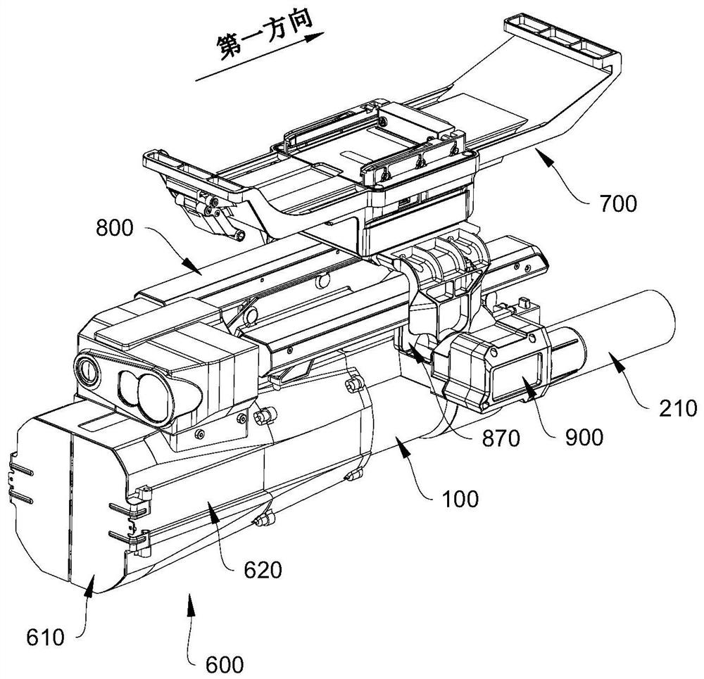
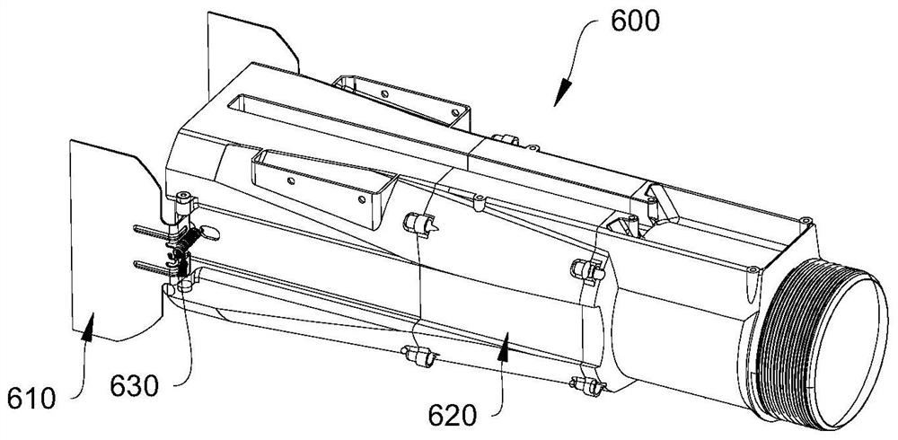
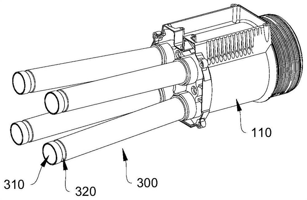

Image

  • Unmanned aerial vehicle
  • Unmanned aerial vehicle
  • Unmanned aerial vehicle

Examples


Embodiment Construction

[0041] The conception and technical effects of the present invention will be clearly and completely described below in conjunction with the embodiments, so as to fully understand the purpose, features and effects of the present invention. Apparently, the described embodiments are only some of the embodiments of the present invention, rather than all of them. Based on the embodiments of the present invention, other embodiments obtained by those skilled in the art without creative efforts belong to The protection scope of the present invention.

[0042]In the description of the embodiments of the present invention, if it involves orientation description, for example, the orientation or positional relationship indicated by "upper", "lower", "front", "back", "left", "right" etc. is based on the drawings The orientations or positional relationships shown are only for the convenience of describing the present invention and simplifying the description, and do not indicate or imply th...


PUM


Abstract

The invention discloses an unmanned aerial vehicle, which is used for projecting an emission head, and comprises an air outlet pipe used for being connected with the emission head; an air cylinder used for storing compressed air; and a driving module. The air cylinder and the air outlet pipe are both connected with the driving module, and the driving module is used for driving the compressed air to be sprayed out through the air outlet pipe. The number of components of the unmanned aerial vehicle is small, the structure can be simplified, and the cost can be reduced.

Description

technical field [0001] The invention relates to the field of unmanned aerial vehicles, in particular to an unmanned aerial vehicle. Background technique [0002] With the continuous development of UAV technology, its application scope is becoming more and more extensive. For example, the combination of UAV and net gun can realize arrest. The use of drones to launch net guns has a long range and accurate positioning. It can perform long-distance and accurate projections during capture, improve capture capabilities, and ensure the safety of your own personnel. Usually, when using a UAV to project a net gun, it is necessary to fix the catch net on the UAV, and after the UAV flies to a predetermined position, unfix the catch net and project it out to realize the capture. However, in the related art, the UAV has a large number of parts and a complicated structure. Contents of the invention [0003] The present invention aims to solve at least one of the technical problems exi...

Claims


Application Information

Patent Timeline
Patent Type & Authority Applications(China)
IPC IPC(8): B64D1/02B64C39/02F16F15/04
CPCB64D1/02B64C39/02F16F15/04B64U2101/00
Inventor 丛保卫杨君杰丛王
Owner HARWAR INT AVIATION TECH SHENZHEN
Why Eureka
Try Eureka