Pump components, compressors and air conditioners

A technology of components and pump bodies, applied in pump components, machines/engines, liquid fuel engines, etc., can solve problems such as vibration and noise, chaotic flow field in the cavity, and reducing the reliability of vane compressors

Active Publication Date: 2021-04-27
GREE ELECTRIC APPLIANCES INC
View PDF9 Cites 0 Cited by
  • Summary
  • Abstract
  • Description
  • Claims
  • Application Information

AI Technical Summary

Problems solved by technology

[0004] But at the same time, the problem is that the minimum distance of the axial exhaust hole along the width direction of the slide must be smaller than the width of the slide, otherwise it will cause gas crossing between the front and rear chambers
And the closer to the exhaust end position, due to the limitation of size, the smaller the exhaust port is at this position. In order to reduce the exhaust speed of the vane compressor, the axial exhaust holes of the vane compressor are generally located in different positions. There will be multiple exhaust outlets. Although this arrangement can solve the above problems, it brings new problems
[0005] like figure 1 As shown, it is the exhaust velocity curve diagram with 3 exhaust ports. When the vane of the vane compressor sweeps the first exhaust port 1' (the first exhaust port 1' is closed), due to the exhaust port If one is missing, the exhaust speed will change suddenly, and the same is true when sweeping through the second exhaust port 2' and the third exhaust port 3', which will cause the flow field of the cavity to be chaotic, causing the main shaft, cylinder, and slide to be affected. Sudden changes in force lead to vibration and noise. At the same time, every time the main shaft of the vane compressor rotates once, the same valve will open and close multiple times (the same number as the vanes), which reduces the reliability of the vane compressor.

Method used


Image

  • Pump components, compressors and air conditioners
  • Pump components, compressors and air conditioners
  • Pump components, compressors and air conditioners

Examples


Embodiment Construction

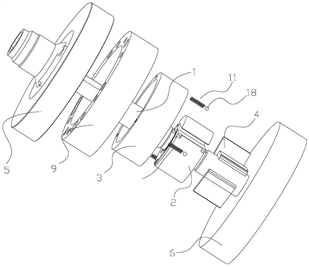
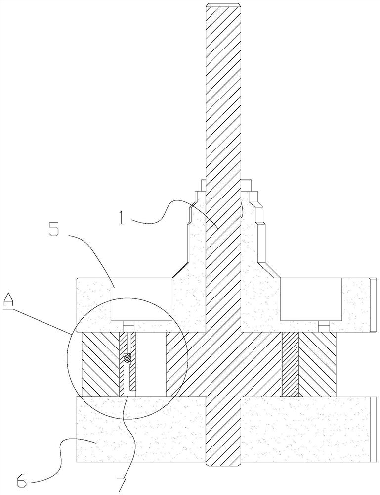
[0037] see in conjunction Figure 2 to Figure 14 As shown, according to the embodiment of the present application, the pump body assembly includes a main shaft 1, a flange, a cylinder seat 9, a cylinder 3 and a sliding piece 4, the main shaft 1 includes a convex portion 2, and a plurality of sliding pieces 4 are arranged on the convex portion at intervals along the circumferential direction. On the part 2, the flange, cylinder 3, sliding piece 4 and convex part 2 enclose a compression chamber 10, and the cylinder 3 is arranged in the cylinder seat 9. The cylinder 3 is eccentrically arranged relative to the main shaft 1, and can rotate synchronously with the main shaft 1. The cylinder 3 Rotation only, the cylinder 3 is provided with a first exhaust channel 7 corresponding to each compression chamber 10, a second exhaust channel 8 is opened on the flange, and a first exhaust channel 7 is provided with a control first exhaust channel 7. Open or close the exhaust valve assembly 11...


PUM


Abstract

The application provides a pump body assembly, a compressor and an air conditioner. The pump body assembly includes a main shaft (1), a flange, a cylinder seat (9), a cylinder (3) and slides (4), the main shaft (1) includes a convex part (2), and a plurality of slides (4) along the circumference The flange, cylinder (3), sliding plate (4) and convex part (2) enclose a compression chamber (10), the cylinder (3) only rotates on its own, and the cylinder (3) corresponds to Each compression chamber (10) is provided with a first exhaust channel (7), the flange is provided with a second exhaust channel (8), and the first exhaust channel (7) is provided with a first exhaust channel (7). Passage (7) opens or closes the exhaust valve assembly (11). According to the pump body assembly of the present application, sudden changes in the exhaust speed can be effectively avoided, the frequency of opening and closing of the exhaust valve assembly can be reduced, and the reliability and stability of the operation of the compressor can be ensured.

Description

technical field [0001] The present application relates to the technical field of air conditioning, in particular to a pump body assembly, a compressor and an air conditioner. Background technique [0002] The sliding vane compressor has the advantages of larger displacement than other types of compressors in the same volume and no eccentricity of the main shaft. However, the sliding vane of the sliding vane compressor is in line contact with the inner wall of the cylinder, and the oil film is not easy to form at the contact position, and the frictional power consumption is large. In order to solve the above problems, in the prior art, the sliding vane compressor generally adopts the side exhaust method of the cylinder to exhaust, but the side row of the cylinder will cause the phenomenon of gas crossing between the front and rear sliding vanes near the exhaust port, and then Increased compressor leakage. The traditional exhaust valve is a reed valve. When the valve is opene...

Claims


Application Information

Patent Timeline
Patent Type & Authority Patents(China)
IPC IPC(8): F04C18/344F04C29/00F04C29/12
CPCF04C18/3445F04C29/00F04C29/128
Inventor 罗发游何洋万鹏凯扶峥邹鹏任丽萍
Owner GREE ELECTRIC APPLIANCES INC
Why Eureka
Try Eureka