LED vehicle lamp module

A technology of LED car lights and LED chips, which is applied in the direction of headlights, motor vehicles, road vehicles, etc., can solve the problems of interference from oncoming vehicles, difficult to match the luminous effect of car lights, etc., to avoid glare, improve assembly firmness, The effect of tight installation

Active Publication Date: 2020-11-24
ZHUHAI CITY ZHENGYUAN OPTOELECTRONICS TECH
View PDF19 Cites 2 Cited by
  • Summary
  • Abstract
  • Description
  • Claims
  • Application Information

AI Technical Summary

Problems solved by technology

For low-power LED car lights, there are not many light beams directed directly ahead, which will not cause glare, but for high-power LED car lights, especially LED car lights used as high beams, the power of the LED chip 14 Very large, resulting in excessive brightness to the front of the LED lights, often forming extremely bright spots directly in front of the LED lights, such as ring-shaped high-brightness spots, which often cause serious interference to oncoming vehicles
[0010] On the other hand, since the light-transmitting member 13 is arranged not far in front of the LED chip 14, that is, the distance between the LED chip and the bottom of the reflective cup 11 is relatively short, the light beam emitted by the LED chip 14 is not much toward the side and rear. , making it difficult to match the luminous effect of traditional car lights such as current halogen lamps and xenon lamps

Method used


Image

  • LED vehicle lamp module
  • LED vehicle lamp module
  • LED vehicle lamp module

Examples


Embodiment Construction

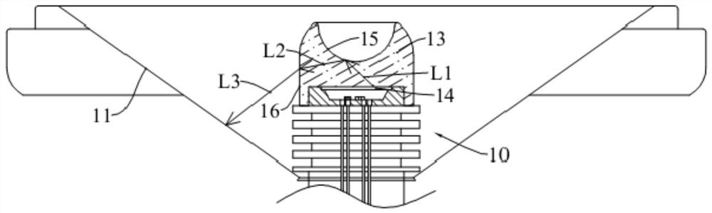
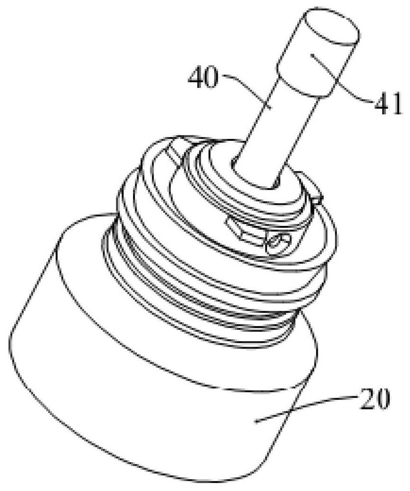
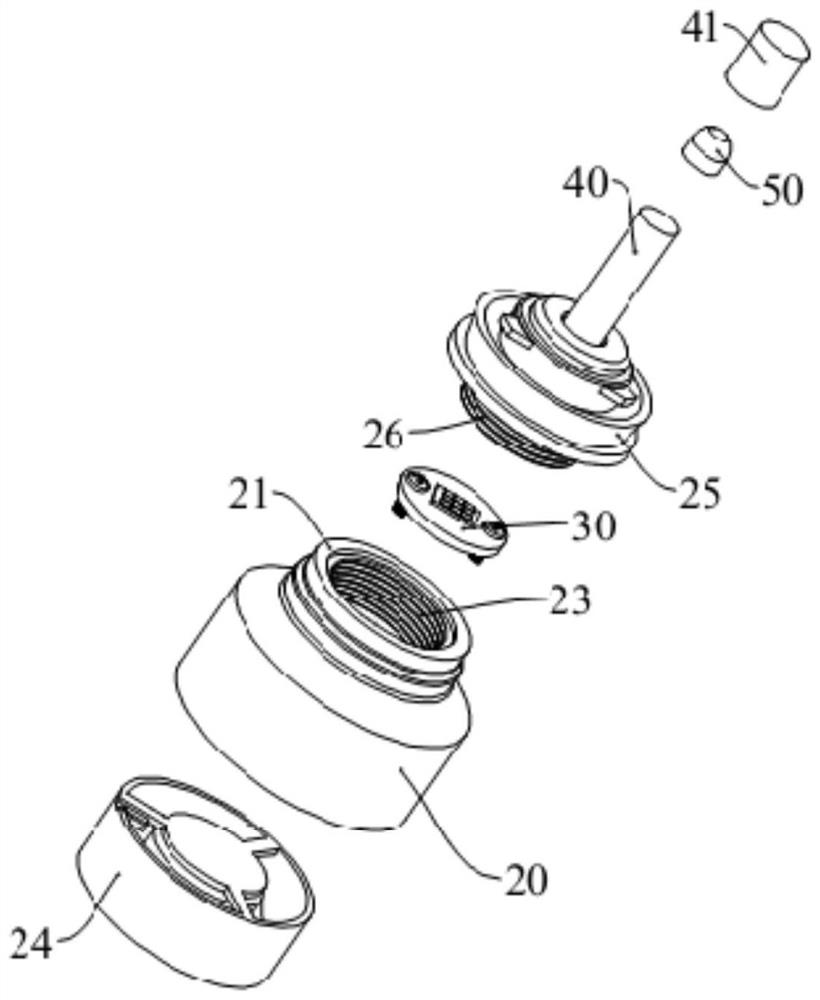
[0037] see figure 2 and image 3 , the present embodiment has a base 20, the bottom of the base 20 is provided with a cooling fan 24, for example, the bottom of the base 20 is provided with an accommodation chamber, and the cooling fan 24 is installed in the accommodation chamber. The cooling fan 24 is used to blow out the heat generated by the LED chip, thereby rapidly reducing the temperature of the LED chip. The substrate 30 is installed in the base 20, and the upper end of the base 20 is provided with a raised portion 21, and the raised portion 21 extends from the upper surface of the base 20, and the raised portion 21 is a circular columnar structure, and the The inner wall of the portion 21 is provided with an internal thread 23 .

[0038] The upper end of the base 20 is provided with a mounting base 25, and the inside of the mounting base 25 is provided with a mounting assembly. The mounting assembly is used to fix the light guide 40 in the mounting base 25. One sec...


PUM


Abstract

The invention provides an LED vehicle lamp module, including a circuit board, wherein at least one LED chip is arranged on the circuit board; a light guide piece is arranged on one side of the light-emitting face of the LED chip, the first end of the light guide piece faces the LED chip, a lens assembly is arranged at the second end of the light guide piece and comprises a first lens and a secondlens, the first surface of the first lens faces the second end of the light guide piece, and a concave conical face is arranged on the second surface of the first lens. The second lens comprises a topwall, the top wall is arranged on the outer side of the second surface of the first lens, and the surface, away from the first lens, of the top wall is a convex arc surface. The invention is appliedto a high-power LED vehicle lamp; the defect that an LED area light source only emits light in the forward direction can be overcome, the light-emitting direction is changed, the light-emitting intensity on the rear side is enhanced, the light distribution effect comparable to halogen and xenon lamps is achieved through effective cooperation with secondary light distribution of a reflecting coverof a vehicle lamp, and high-brightness dazzle light is prevented from appearing in front of the LED vehicle lamp module.

Description

technical field [0001] The invention relates to the field of auto parts, in particular to an LED lamp module for automobiles. Background technique [0002] LED light-emitting devices are used as lamps, and have the advantages of energy saving, long service life, and high luminance, and have been widely used in various types of lamps such as lighting and decoration. LED lamps are usually loaded in a casing to form an LED lighting device, and the LED lighting device is used to replace traditional incandescent bulbs, xenon lamps or halogen lamps installed in lamps. [0003] The LED car light module is a car light module that includes an LED light-emitting device, and the LED car light is usually installed at the center of a bowl-shaped reflector. Because the LED chip emits light toward the front, the emitted light beam will not be emitted from the side, which will cause the LED car light reflector to receive or receive weaker light intensity and cannot complete the secondary l...

Claims


Application Information

Patent Timeline
Patent Type & Authority Applications(China)
IPC IPC(8): F21S41/141F21S41/24F21S41/25F21V19/00F21W107/10F21Y115/10
CPCF21S41/141F21S41/24F21S41/25F21V19/001F21W2107/10F21Y2115/10
Inventor 潘殿波
Owner ZHUHAI CITY ZHENGYUAN OPTOELECTRONICS TECH
Why Eureka
Try Eureka