Optical imaging system, image capturing module and electronic device

An optical imaging system and optical axis technology, applied in optics, optical components, instruments, etc., can solve the problems of not being able to achieve full-screen visual effects, unfavorable packaging of the camera lens under the screen, and large head of the camera lens, so as to satisfy the camera experience , Broaden the field of vision, and the effect of good imaging ability

Pending Publication Date: 2020-11-24
JIANGXI JINGCHAO OPTICAL CO LTD
View PDF0 Cites 1 Cited by
  • Summary
  • Abstract
  • Description
  • Claims
  • Application Information

AI Technical Summary

Problems solved by technology

[0003] In the process of implementing this application, the inventors found that there are at least the following problems in the prior art: Although the traditional camera lenses mounted on portable electronic products can meet the miniaturization requirements, the head of the camera lens is relatively large, which is not conducive to taking pictures. The lens is packaged under the screen, and the screen opening is large, which cannot achieve the visual effect of a full screen

Method used


Image

  • Optical imaging system, image capturing module and electronic device
  • Optical imaging system, image capturing module and electronic device
  • Optical imaging system, image capturing module and electronic device

Examples


no. 1 example

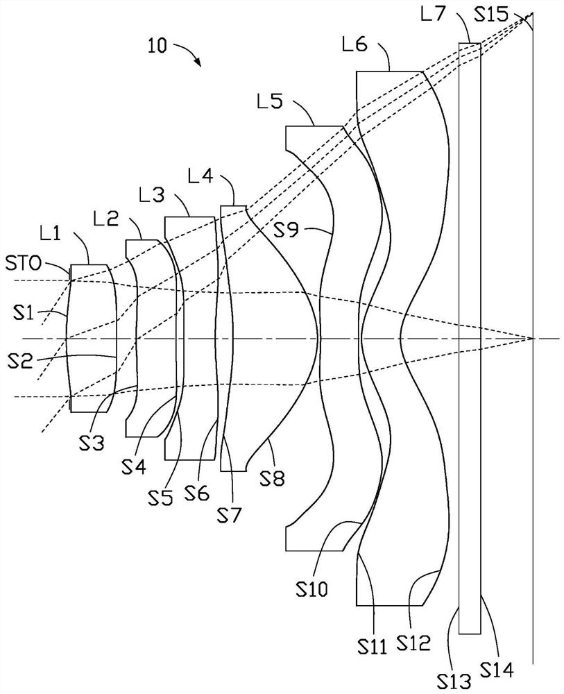
[0104] Please refer to figure 1 and figure 2 , the optical imaging system 10 of the first embodiment includes in sequence from the object side to the image side: a diaphragm STO, a first lens L1 with positive refractive power, a second lens L2 with positive refractive power, and a third lens L2 with negative refractive power. Lens L3, fourth lens L4 with positive refractive power, fifth lens L5 with negative refractive power, sixth lens L6 with negative refractive power, and infrared filter L7.

[0105] Wherein, the object side S1 of the first lens L1 is convex at the optical axis, and the image side S2 is convex at the optical axis; the object side S3 of the second lens L2 is convex at the optical axis, and the image side S4 is convex at the optical axis. Concave surface; the object side S5 of the third lens L3 is a convex surface at the optical axis, and the image side S6 is concave at the optical axis; the object side S7 of the fourth lens L4 is concave at the optical axi...

no. 2 example

[0118] Please refer to image 3 and Figure 4 , the optical imaging system 10 of the second embodiment includes in sequence from the object side to the image side: a stop STO, a first lens L1 with positive refractive power, a second lens L2 with positive refractive power, and a third lens L2 with negative refractive power. Lens L3, fourth lens L4 with positive refractive power, fifth lens L5 with negative refractive power, sixth lens L6 with negative refractive power, and infrared filter L7.

[0119] Wherein, the object side S1 of the first lens L1 is a convex surface at the optical axis, and the image side S2 is concave at the optical axis; the object side S3 of the second lens L2 is convex at the optical axis, and the image side S4 is at the optical axis. Convex surface; the object side S5 of the third lens L3 is concave at the optical axis, and the image side S6 is concave at the optical axis; the object side S7 of the fourth lens L4 is concave at the optical axis, and the...

no. 3 example

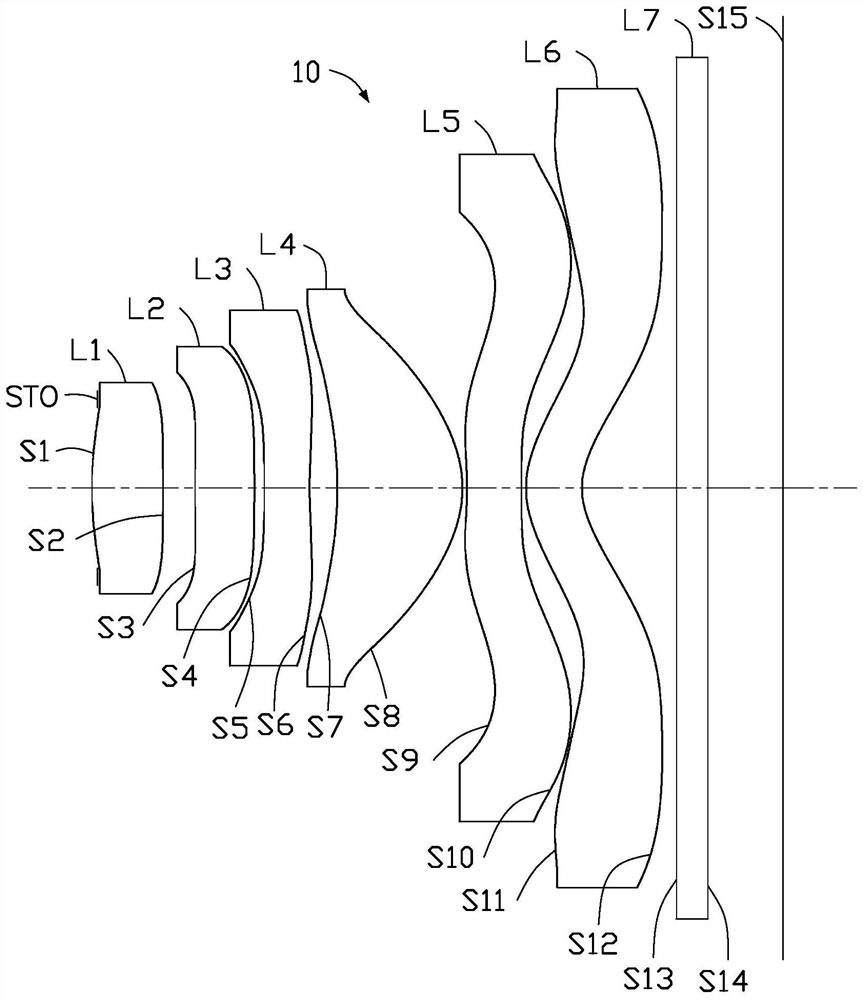
[0133] Please refer to Figure 5 and Figure 6 , the optical imaging system 10 of the third embodiment includes in sequence from the object side to the image side: a stop STO, a first lens L1 with positive refractive power, a second lens L2 with negative refractive power, and a third lens L2 with negative refractive power. Lens L3, fourth lens L4 with positive refractive power, fifth lens L5 with negative refractive power, sixth lens L6 with negative refractive power, and infrared filter L7.

[0134] Wherein, the object side S1 of the first lens L1 is a convex surface at the optical axis, and the image side S2 is a convex surface at the optical axis; the object side S3 of the second lens L2 is concave at the optical axis, and the image side S4 is at the optical axis. Convex surface; the object side S5 of the third lens L3 is a convex surface at the optical axis, and the image side S6 is concave at the optical axis; the object side S7 of the fourth lens L4 is concave at the op...


PUM


Abstract

The invention provides an optical imaging system, an image capturing module and an electronic device. The optical image imaging system includes, in order from an object side to an image side: a firstlens with positive refractive power, the object-side surface of the first lens being convex at an optical axis; a second lens with refractive power; a third lens with refractive power; a fourth lens with positive refractive power, the image-side surface of the fourth lens being convex at the optical axis; a fifth lens with refractive power; a sixth lens with refractive power, the object-side surface of the sixth lens being a convex surface at the optical axis, and the image-side surface of the sixth lens being a concave surface at the optical axis; the optical imaging system satisfies the following conditions: 0.5 < f1/f26 < 1.6, wherein f26 is the combined focal length of the second lens, the third lens, the fourth lens, the fifth lens and the sixth lens, and f1 is the effective focal length of the first lens. The optical imaging system has the advantages of wide viewing angle and head miniaturization.

Description

technical field [0001] The invention relates to optical imaging technology, in particular to an optical imaging system, an imaging module and an electronic device. Background technique [0002] In recent years, full-screen mobile phones have gradually been favored by consumers. It can be seen that high screen-to-body ratio has become a development trend of mobile phones. Under this trend, the size of mobile phone camera lenses is required to be miniaturized, while ensuring high imaging Quality, so the specification requirements for camera lenses are getting higher and higher. [0003] In the process of implementing this application, the inventors found that there are at least the following problems in the prior art: Although the traditional camera lenses mounted on portable electronic products can meet the miniaturization requirements, the head of the camera lens is relatively large, which is not conducive to taking pictures. The lens is packaged under the screen, and the s...

Claims


Application Information

Patent Timeline
Patent Type & Authority Applications(China)
IPC IPC(8): G02B13/00G02B13/18G02B13/06
CPCG02B13/0045G02B13/06G02B13/18
Inventor 杨健李明
Owner JIANGXI JINGCHAO OPTICAL CO LTD
Why Eureka
Try Eureka