Damp-proof electromagnetic flow meter

An electromagnetic flowmeter and flow rate technology, which is applied in the field of flowmeters, can solve the problems of reducing the distance, not paying attention to the moisture resistance of the terminals of the electromagnetic flowmeter, reducing the cost and complexity of the system, and achieving the effect of increasing the sealing

Inactive Publication Date: 2020-11-27
陕西诺盈自动化仪表有限公司
View PDF3 Cites 0 Cited by
  • Summary
  • Abstract
  • Description
  • Claims
  • Application Information

AI Technical Summary

Problems solved by technology

[0003] In response to this, Chinese Patent No. CN204694303U proposes an electromagnetic flowmeter, which is suitable for measuring various media with different characteristics, reducing the cost and complexity of the system; Chinese Patent No. CN201653472U proposes an electromagnetic flowmeter, which uses a shorter measuring tube, And reduce the distance between the two electrodes, and the coil can be consistent with the small-diameter coil to reduce the weight and cost of the entire electromagnetic flowmeter; Chinese patent No. CN209264032U proposes an electromagnetic flowmeter, which solves the problem of electromagnetic flow Most of the electromagnetic flowmeters are fixed on the pipeline by bolts and nuts, and disassembly and assembly are more troublesome.
However, none of the above patents paid attention to the moisture-proofing of the terminals of the electromagnetic flowmeter. The electromagnetic flowmeter is usually installed on the liquid pipeline, and the moisture is relatively large, so it is easy to make the connection between the terminal and the external wire get wet and malfunction. Bolts are usually used to install the protective moisture-proof casing on the terminals of the electromagnetic flowmeter. On the one hand, the installation and disassembly are cumbersome, and on the other hand, the bolts are usually directly exposed to the outside world, which is easy to be damp and rusted, making it difficult to disassemble.

Method used


Image

  • Damp-proof electromagnetic flow meter
  • Damp-proof electromagnetic flow meter
  • Damp-proof electromagnetic flow meter

Examples


Embodiment 1

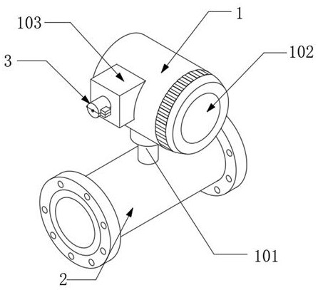
[0025] like figure 1 As shown, a moisture-proof electromagnetic flowmeter includes a main body 1, a connecting shaft 101 is welded to the bottom of the main body 1, a flow guide tube 2 is fixedly connected to the bottom of the connecting shaft 101, and a flow display screen 102 is arranged on the outer surface of the main body 1. The outer surface of the main body 1 is fixedly connected with a fixed block 103, the side of the fixed block 103 away from the main body 1 is connected with a protective component 3 and is fixedly connected with a terminal 104, the number of the terminal 104 is two, the external wire and the terminal 104 Connection, the liquid pipeline is connected with the guide tube 2, and when the internal liquid flows in the guide tube 2, the volume of the conductive medium in the tube is measured according to Faraday's law of electromagnetic induction, and displayed on the flow display screen 102 .

Embodiment 2

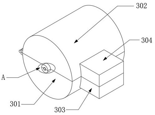
[0027] On the basis of Example 1, such as Figure 2-3 As shown, the protective assembly 3 includes a first protective shell 301 and a second protective shell 302, the first protective shell 301 is welded on the side wall of the fixed block 103, and one side of the first protective shell 301 is connected to the second protective shell 302 by a hinge. Rotationally connected, the other side of the first protective shell 301 and one side of the second protective shell 302 are respectively fixedly connected with a first limiting block 303 and a second limiting block 304, and the first limiting block 303 and the second A clamping mechanism is provided between the limit blocks 304, the second protective shell 302 is closely against the side wall of the fixed block 103, and the contact part is fixedly connected with a gasket 310, through the set first protective shell 301 and the second protective shell 302, the first protective shell 301 and the second protective shell 302 are closel...

Embodiment 3

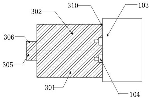
[0029] On the basis of embodiment one and embodiment two, such as Figure 4 As shown, the side wall of the first protective shell 301 and the side wall of the second protective shell 302 are respectively welded with a first clamping block 305 and a second clamping block 306, and the top of the first clamping block 305 is provided with a first clamping groove 307, The bottom of the second clamping block 306 is provided with the second clamping groove 308 that is compatible with the first clamping groove 307, and the inner walls of the first clamping groove 307 and the second clamping groove 308 are all fixedly connected with rubber pads 309, through the provided The first clamping block 305, the second clamping block 306, the first clamping slot 307 and the second clamping slot 308 tightly squeeze the external wires entering the inside of the protection component 3, and the rubber pad 309 provided in cooperation further increases the protection component 3, prevents moist air f...


PUM


Abstract

The invention discloses a damp-proof electromagnetic flow meter. The flow meter comprises a main body, a connecting shaft is welded to the bottom of the main body, a flow guide pipe is fixedly connected to the bottom of the connecting shaft, a flow display screen is arranged on the outer surface of the main body, a fixing block is fixedly connected to the outer surface of the main body, and a protection assembly and a wiring terminal are connected to the side, away from the main body, of the fixing block. According to the damp-proof electromagnetic flow meter, through the arrangement of a first protective shell, a second protective shell, a first clamping block and a second clamping block, water is prevented from entering the interior of the protection assembly and contacting the wiring terminal, the first protective shell and the second protective shell are conveniently opened and closed through an arranged clamping mechanism, and the situation that a common device is fixed by bolts,the bolts are directly exposed to an external thread and can be easily damped and rusted, and thus the device is difficult to disassemble is avoided.

Description

technical field [0001] The invention relates to the field of flowmeters, in particular to a moisture-proof electromagnetic flowmeter. Background technique [0002] Simply put, the electromagnetic flowmeter is composed of a flow sensor transmitter. The installation requirement of the electromagnetic flowmeter is that it must be installed at the lowest point of the pipeline or the vertical section of the pipeline, but it must be in the case of a full pipe. The requirement for the pipe section is 5D in the front and 3D in the back, so as to ensure the use of the electromagnetic flowmeter and the accuracy requirements. [0003] In response to this, Chinese Patent No. CN204694303U proposes an electromagnetic flowmeter, which is suitable for measuring various media with different characteristics, reducing the cost and complexity of the system; Chinese Patent No. CN201653472U proposes an electromagnetic flowmeter, which uses a shorter measuring tube, And reduce the distance betwee...

Claims


Application Information

Patent Timeline
IPC IPC(8): G01F15/14G01F1/58
CPCG01F1/58G01F15/14
Inventor 李军荣
Owner 陕西诺盈自动化仪表有限公司
Why Eureka
Try Eureka