
Remote monitoring management system and method

A technology of remote monitoring and management system, applied in general control systems, control/regulation systems, program control, etc., can solve the problems of difficult coordination and synchronization, time-consuming, and inability to perform global monitoring, so as to improve the efficiency of construction supervision and save time. Effect

Inactive Publication Date: 2020-11-27
河南高建工程管理有限公司
View PDF0 Cites 1 Cited by
  • Summary
  • Abstract
  • Description
  • Claims
  • Application Information

AI Technical Summary

Problems solved by technology

[0003] Project quality and safe production are the top priorities in the construction process. The method of manual supervision has many disadvantages. At the same time, only one area can be inspected, and overall monitoring cannot be carried out. It is also a challenge for multiple inspectors to coordinate and synchronize with each other. Therefore, it is time-consuming to use manual supervision and monitoring methods, and the efficiency of construction supervision is also relatively low

Method used


Image

  • Remote monitoring management system and method
  • Remote monitoring management system and method
  • Remote monitoring management system and method

Examples


Embodiment 1

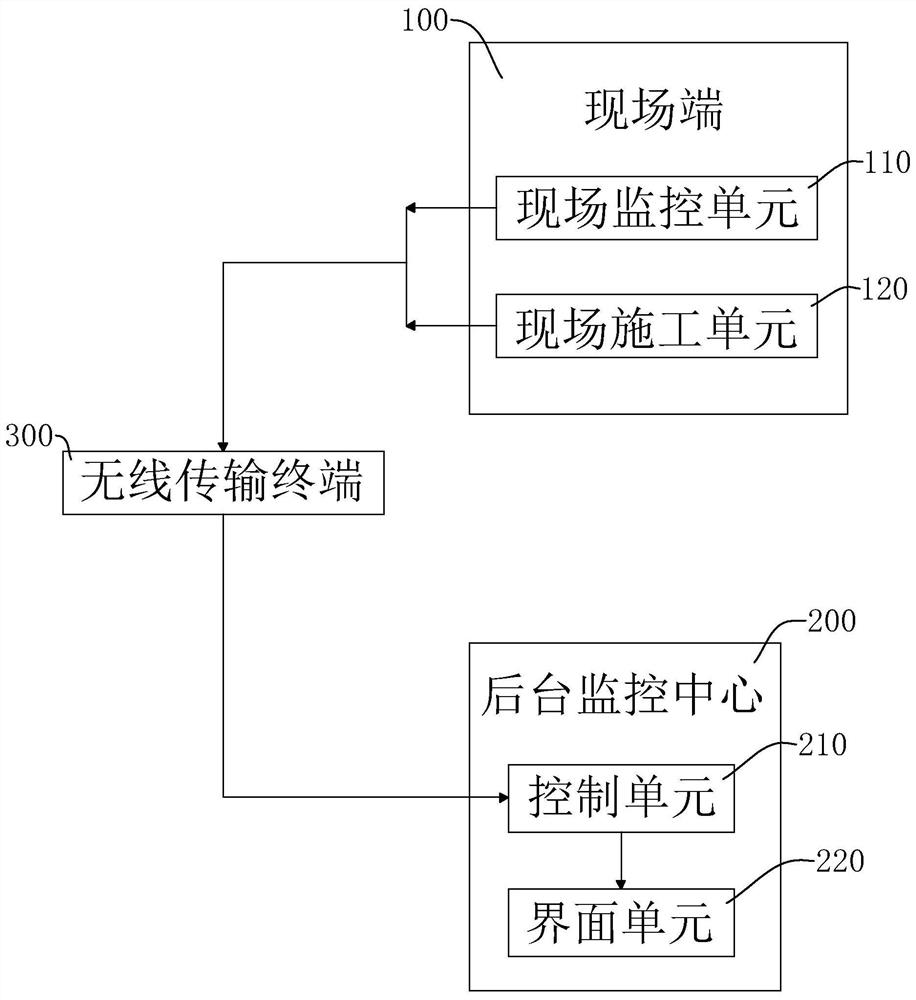
[0041] Please refer to figure 1 , is a remote monitoring and management system disclosed in this application, as shown in the figure, it includes a field terminal 100 and a background monitoring center 200, wherein, the field terminal 100 and the background monitoring center 200 are connected by communication, preferably, in this embodiment , the field terminal 100 communicates with the background monitoring center 200 through the wireless transmission terminal 300, which saves the cumbersome wiring compared to wired communication.

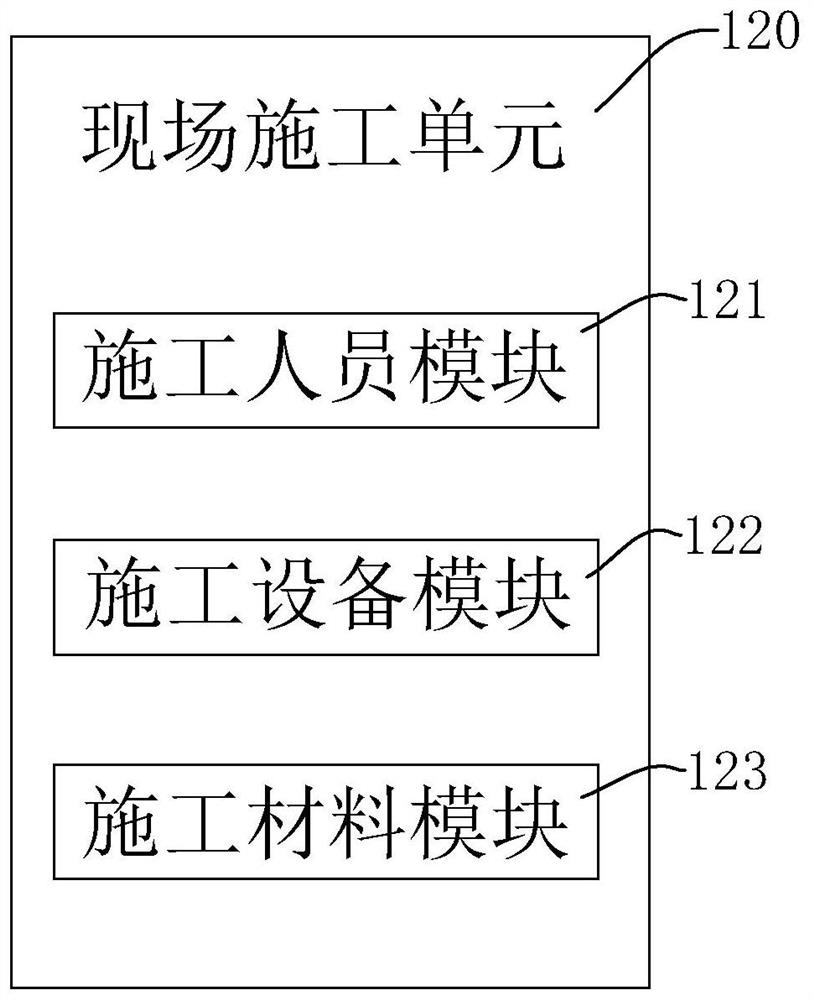
[0042] Wherein, in this embodiment, the site terminal 100 includes a site monitoring unit 110 and a site construction unit 120, and the site monitoring unit 110 is used to monitor the construction situation of the construction site.

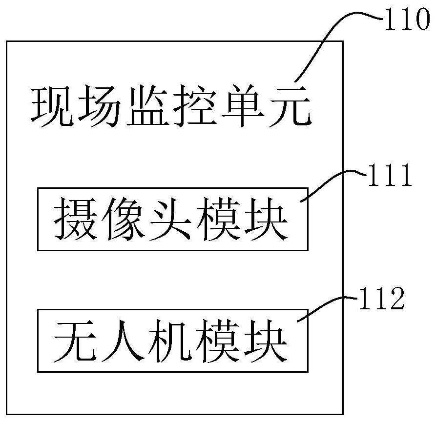
[0043] Please refer to figure 2 Specifically, the on-site monitoring unit 110 includes a camera module 111 and an unmanned aerial vehicle module 112. In this embodiment, the camera module 111 is used in conjunction...

Embodiment 2

[0053] Please refer to Figure 4 , is another embodiment of the present application. As shown in the figure, the difference between this embodiment and the previous embodiment is that the control unit 210 also includes a connection judgment module 217, a quality judgment module 218, and a quality alarm module 219, wherein , the connection judging module 217 and the quality judging module 218 are respectively connected to the processing module 211 by communication, that is, the connection judging module 217 can judge whether the background monitoring center 200 and the field terminal 100 are successfully connected to each other, so as to avoid the situation that the networking is unsuccessful and affect the background Normal monitoring of the monitoring center 200; through the quality judgment module 218, it can be judged whether the picture or video of the on-site monitoring sent by the camera module 111 and the UAV module 112 meets the requirements, for example, whether the pi...


PUM


Abstract

The invention relates to a remote monitoring management system. The system comprises a field terminal and a background monitoring center, wherein the field terminal is in communication connection withthe background monitoring center, the field terminal comprises a field monitoring unit, the background monitoring center comprises a control unit and an interface unit, the control unit is in communication connection with the field monitoring unit and the interface unit, the control unit comprises a processing module and a storage module, the processing module is in communication connection withthe storage module, the interface unit comprises a project division module, a project map module, a project marking module and a project image module, the project map module is in communication connection with the processing module, the project division module and the project marking module, and the project image module is in communication connection with the processing module. The system has theeffects of saving time and improving the construction supervision efficiency.

Description

technical field [0001] This application relates to the technical field of engineering supervision, in particular to a remote monitoring management system and its method. Background technique [0002] At present, project supervision refers to the supervision unit with relevant qualifications entrusted by Party A to represent Party A to Party B in accordance with the project construction documents approved by the state, laws and regulations related to project construction, project construction supervision contracts and other project construction contracts. It is a professional service activity for the implementation and monitoring of engineering construction. [0003] Project quality and safe production are the top priorities in the construction process. The method of manual supervision has many disadvantages. At the same time, only one area can be inspected, and overall monitoring cannot be carried out. It is also a challenge for multiple inspectors to coordinate and synchron...

Claims


Application Information

Patent Timeline
Patent Type & Authority Applications(China)
IPC IPC(8): G05B19/042
CPCG05B19/0423G05B2219/23051
Inventor 张丰华赫超红王伟朱青松尚小静任记公郭震孙军旗
Owner 河南高建工程管理有限公司
Learn More