Automatic assembling and buckling device for elastic buckle, and control method thereof

An automatic assembly and elastic buckle technology, applied in the direction of electrical components, electrical components, etc., can solve problems such as material falling off, circuit board deformation, and chip failure on the circuit board

Active Publication Date: 2020-11-27
HUIZHOU DESAY SV AUTOMOTIVE
View PDF17 Cites 2 Cited by
  • Summary
  • Abstract
  • Description
  • Claims
  • Application Information

AI Technical Summary

Problems solved by technology

[0010] The purpose of the present invention is to solve the problem of manual assembly of existing products, which may cause inaccurate assembly force control, easily cause circuit board deformation, and even cause chip failure on the circuit board. Buckle, relying on hard-to-hard contact, there is vibration, easy to produce collision, material fall off, fastening operation is cumbersome, low work efficiency, insufficient reliability, unstable process quality control

Method used


Image

  • Automatic assembling and buckling device for elastic buckle, and control method thereof
  • Automatic assembling and buckling device for elastic buckle, and control method thereof
  • Automatic assembling and buckling device for elastic buckle, and control method thereof

Examples


Embodiment 1

[0129] A control method for automatic assembly of elastic buckles based on the above-mentioned automatic assembly and fastening device for elastic buckles is carried out according to the following steps:

[0130] Step 1, start: turn on the device power switch (set on the device panel), turn on the air source switch (not shown in the figure), the system is initialized, and each unit is in the standby state (at this time, the standby indicator 3075 light is yellow, such as Figure 15 shown);

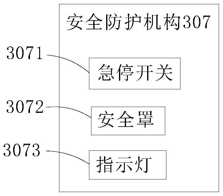
[0131] Step 2, safety protection: there is an emergency stop switch 3071 on the panel of the device, press this switch for emergency stop in case of abnormality, and a vacuum status display 3181 (divided into two displays for circuit board vacuum and aluminum shell vacuum); There is a safety cover 3072, and there is a safety grating 3074 on the front (set on both sides of the front of the safety cover 3072), when there is external interference, it will automatically cut off all dangerous i...

Embodiment 2

[0146] Step 1 to step 8 of the present embodiment 2 are the same as embodiment 1, the difference is from step 9 to step 11, specifically as follows:

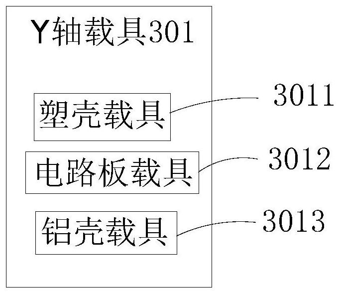
[0147] Step 9, circuit board suction: Z1-axis circuit board fastening mechanism 304 integrates vacuum suction cup 318, color mark sensor 103, pressure sensor 105 and sliding table cylinder 310, Z1-axis circuit board fastening mechanism 304 is lowered to the circuit board carrier 3012 , the color sensor 103 detects the heat dissipation silica gel (not shown in the figure) on the circuit board 314. If there is silica gel, it is normal. The touch screen 106 synchronously prompts that the carrier has no missing parts. The control panel 106 simultaneously prompts the missing part of the carrier. Under normal circumstances, the vacuum suction cup 318 fits the circuit board 314 to carry out negative pressure suction. The pressure sensor 105 detects the pressure state of the feedback circuit board 314. If the pressure exceeds the safe p...


PUM


Abstract

The invention relates to an automatic assembling and buckling device for an elastic buckle. The automatic assembling and buckling device comprises a signal input unit, a control unit and an executionunit. The signal input unit includes multiple sensors, a touch screen and an operation button, the control unit includes a data acquisition module, a central processor, a closed-loop servo encoder, agas driven module and an electrically driven module, and the execution unit comprises a Y-axis carrier, a Y-axis fourth assembly part buckling mechanism, a Z1-axis second assembly part buckling mechanism, a Z2-axis third assembly part buckling mechanism, an X-axis conveying mechanism, a Y-axis conveying mechanism, a Z-axis conveying mechanism, a static eliminator and a safety protection mechanism.The Y-axis carrier comprises a plastic shell carrier, a circuit board carrier and an aluminum shell carrier. The Y-axis fourth assembly part buckling mechanism comprises a face shell carrier. Compared with devices adopting a traditional method to assemble, the device of the invention is more stable in assembling, is reliable in detection feedback, has the effects of eliminating electrostatic damage, inaccurate buckling, part collision, silica gel falling and overlarge stress risks, and also has the advantages of automatic buckling, high production efficiency and small size.

Description

technical field [0001] The invention relates to the technical field of automatic assembly, in particular to an automatic assembly and fastening device and a control method for elastic buckles. Background technique [0002] The vehicle data transmission assembly product is divided into two parts, the circuit board and the shell. There are a variety of control chips and data processing chips densely distributed on the front and back of the circuit board, which are the core components, and the outer shell is divided into plastic shells, aluminum shells, and surface shells. The circuit board is fixed in the cavity of the plastic case through the buckle of the plastic case. The aluminum case, the surface case and the plastic case each have multiple fastening points, which form a protective shell for the circuit board after fastening with each other. Ground protection function. The existing manual fastening process is prone to inaccurate assembly strength control, which may easi...

Claims


Application Information

Patent Timeline
IPC IPC(8): H05K13/04H05K13/08H05K13/00
CPCH05K13/0015H05K13/0409H05K13/0812H05K13/082
Inventor 张京梁林翔黄麦多
Owner HUIZHOU DESAY SV AUTOMOTIVE
Why Eureka
Try Eureka