A packet mode-hopping time-domain modulation method

A modulation method and time domain technology, applied in the field of lasers, which can solve the problems of small free light range and difficulty in obtaining

Active Publication Date: 2021-07-27
THE HONG KONG POLYTECHNIC UNIV SHENZHEN RES INST +1
View PDF8 Cites 0 Cited by
  • Summary
  • Abstract
  • Description
  • Claims
  • Application Information

AI Technical Summary

Problems solved by technology

[0006] The technical problem to be solved by the present invention is to provide a packet mode-hopping time-domain modulation method for the above-mentioned defects of the prior art, aiming to solve the problem that it is difficult to obtain a very small free light range by using the time-domain modulation method in the prior art The problem

Method used


Image

  • A packet mode-hopping time-domain modulation method
  • A packet mode-hopping time-domain modulation method
  • A packet mode-hopping time-domain modulation method

Examples


Embodiment 1

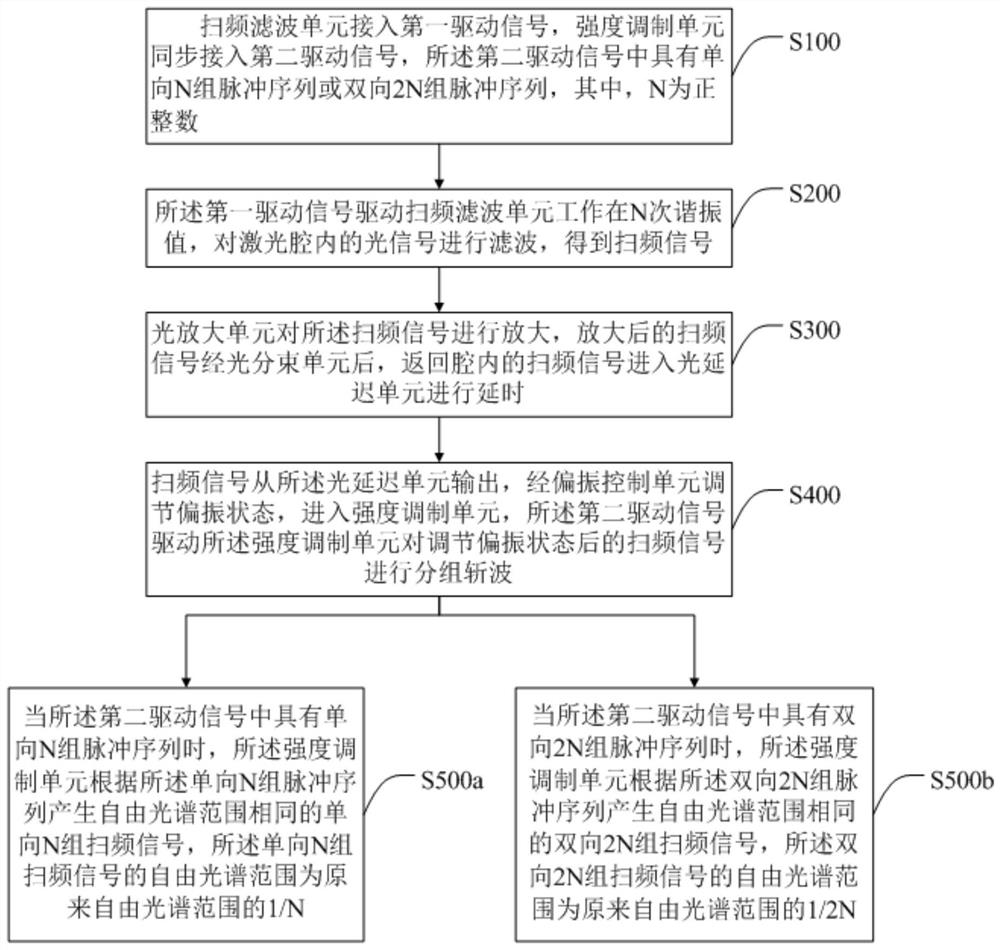
[0079] A Fourier mode-locked laser with unidirectional frequency sweep based on packet mode-hopping time-domain modulation is illustrated by taking triple frequency as an example. Since the tunability of the time-domain signal is much stronger than the tuning performance of the comb filter, it has obvious flexibility advantages. Therefore, the frequency sweeping is performed by introducing an optical intensity modulator (MOD) into the laser cavity instead of a comb filter. Signals are grouped and discretized.

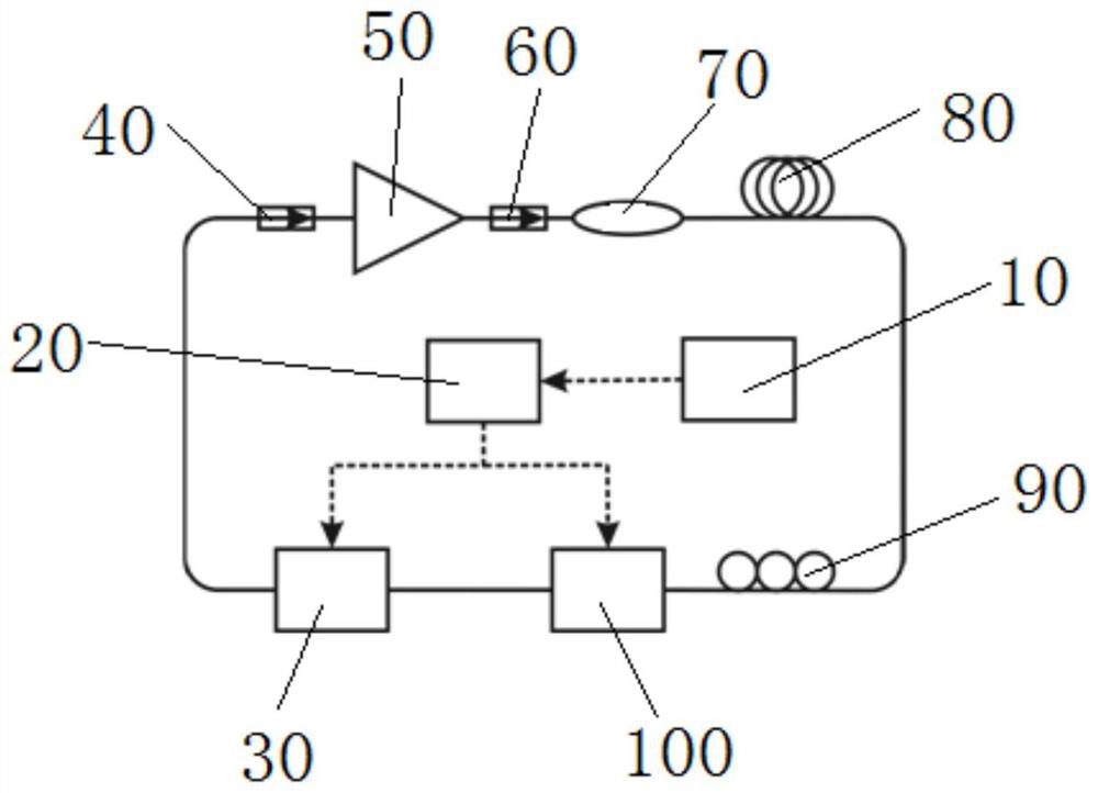
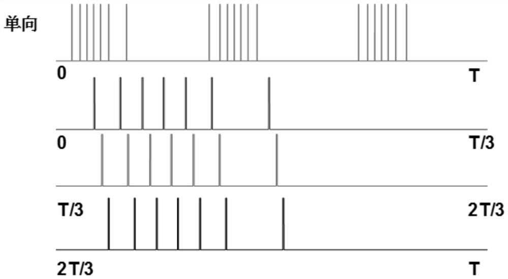
[0080] One-way swept Fourier mode-locked laser based on packet mode-hopping time-domain modulation includes: optical amplifier (OA), optical isolator (ISO), optical beam splitter (BS), fiber delay line (Delay), polarization controller (PC), light intensity modulator (MOD), swept frequency filter (SF), signal generator (SG), clock (CLK) and other components. see Figure 5 , Figure 5 It is to design three sets of one-way discrete frequency sweep pulse sequences loaded...

Embodiment 2

[0083] Two-way frequency-sweeping Fourier mode-locked laser based on packet mode-hopping time-domain modulation, taking triple frequency as an example. Since the tunability of the time-domain signal is much stronger than the tuning performance of the comb filter, it has obvious flexibility advantages. In addition to adding a single-directional sweep signal to the modulator to realize grouped discrete sweep signals, it can also be achieved by giving The modulator applies grouped discrete frequency sweep signals in forward and reverse directions to drive the modulator to output sweep signals with the same frequency and free spectral range. As shown in the figure, the two-way sweeping Fourier mode-locked laser based on packet mode-hopping time-domain modulation includes: optical amplifier (OA), optical isolator (ISO), optical beam splitter (BS), fiber delay line (Delay) , Polarization controller (PC), optical intensity modulator (MOD), swept frequency filter (SF), signal generato...


PUM


Abstract

A group mode-hopping time-domain modulation method provided by the present invention includes: the frequency sweep filter unit is connected to the first driving signal, the intensity modulation unit is synchronously connected to the second driving signal, and the second driving signal has N groups of unidirectional pulses Sequence or two-way 2N groups of pulse sequences; the first drive signal drives the frequency sweep filter unit to work at the Nth resonance value to obtain the frequency sweep signal; the frequency sweep signal enters after passing through the optical amplification unit, optical splitting unit, optical delay unit, and polarization control unit Intensity modulation unit, the second drive signal drives the intensity modulation unit to perform group chopping on the frequency sweep signals after the polarization state is adjusted; the intensity modulation unit generates unidirectional N group frequency sweep signals or bidirectional 2N group frequency sweep signals with the same free spectral range, The free spectral range becomes the original 1 / N or 1 / 2N. The invention obtains a smaller free light range, and at the same time increases the sweeping speed of the Fourier mode-locked laser by N times.

Description

technical field [0001] The invention relates to the technical field of lasers, in particular to a packet mode-hopping time-domain modulation method. Background technique [0002] Fourier mode-locked laser technology is an important technical solution to realize high-speed frequency-sweeping laser light sources, and has potential applications in optical coherent imaging systems, optical sensing, optical communications, and spectral measurement. A length of optical fiber is added in the laser cavity as a delay line so that each wavelength circulates in the cavity once and reaches the frequency-sweeping filter again, and the filter is just tuned to this wavelength to pass it. Therefore, each wavelength does not need to be reconstructed from noise, and the frequency sweep speed is not limited by the time for laser oscillation to settle but only by the tuning speed of the filter. [0003] Due to the combined effects of the dispersion and nonlinearity of the resonant cavity of th...

Claims


Application Information

Patent Timeline
Patent Type & Authority Patents(China)
IPC IPC(8): H04B10/50H04B10/524H04B10/54H01S3/067H01S3/10H01S3/11
CPCH01S3/06791H01S3/10H01S3/10061H01S3/1106H04B10/503H04B10/524H04B10/54
Inventor 黄冬梅李锋卫炳江
Owner THE HONG KONG POLYTECHNIC UNIV SHENZHEN RES INST
Why Eureka
Try Eureka