Unlock instant, AI-driven research and patent intelligence for your innovation.
Connecting tube for stethoscope and ear hook rubber tube connecting assembly
What is Al technical title?
Al technical title is built by PatSnap Al team. It summarizes the technical point description of the patent document.
A technology for connecting components and connecting tubes, which is applied in stethoscopes and other directions, and can solve problems such as the narrowing of lumen sound guide channels, increasing user costs, and the inability of doctors to auscultate with fine audio
Inactive Publication Date: 2020-12-04
WUXI KAISHUN MEDICAL DEVICE MFG CO LTD
View PDF0 Cites 0 Cited by
Summary
Abstract
Description
Claims
Application Information
AI Technical Summary
This helps you quickly interpret patents by identifying the three key elements:
Problems solved by technology
Method used
Benefits of technology
Problems solved by technology
[0004] Secondly, the flash on the lumen wall of the sound-guiding hose at the Y-shaped junction did not completely block one side of the lumen, but because the flash cannot be found visually in the lumen of the sound-guiding hose, it cannot be detected even with audio testing equipment. Effective detection found flashes, so the quality of the product cannot be guaranteed; when this product enters the market and is used by doctors, when listening to patients' subtle audio such as respiratory rales and heart murmurs, it often happens that they cannot hear or can't hear clearly or left and right. Consequences of Unbalanced Hearing
However, about 5% of the sound-guiding hoses in the prior art cannot detect the narrowing of the lumen sound-guiding channel when they are produced, which eventually leads to the doctor’s subtle audio frequency being unable to auscultate.
[0005] Furthermore, if two straight sound-guiding rubber hoses are used to connect with the left earhook and the right earhook respectively, on the one hand the cost of the user is increased, and on the other hand the two straight sound-guiding rubber hoses are respectively connected to the left earhook and the right earhook. After the right earhook is connected, the third sound guide hose needs to be connected. At the junction of the three sound guide hoses, a connector is needed to make the lumens of the three sound guide hoses communicate, so it is very cumbersome and unsightly. After the combination of the sound-guiding rubber hose, the volume of the sound-guiding rubber hose is too large, which is not easy to carry, causing inconvenience to the doctor's use or visits
Method used
Image
Click on the blue label to locate the original text in one second.
Reading with bidirectional positioning of images and text.
Examples
Embodiment 1
[0075] Embodiment 1: in combination with figure 1 , figure 2 , image 3 , Figure 8 Shown, the present invention is described further.
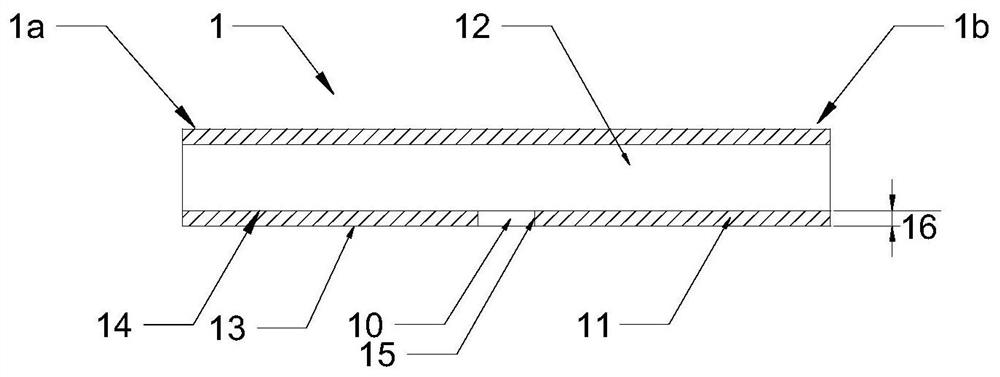
[0076] The stethoscope uses a connecting tube 1, which is a flexible, straight hollow rubber tube. The connecting pipe 1 is provided with a terminal 1a and a terminal B 1b at both ends. The middle part of the connecting pipe 1 is provided with a hole 10 passing through the pipe wall 11 on one side.
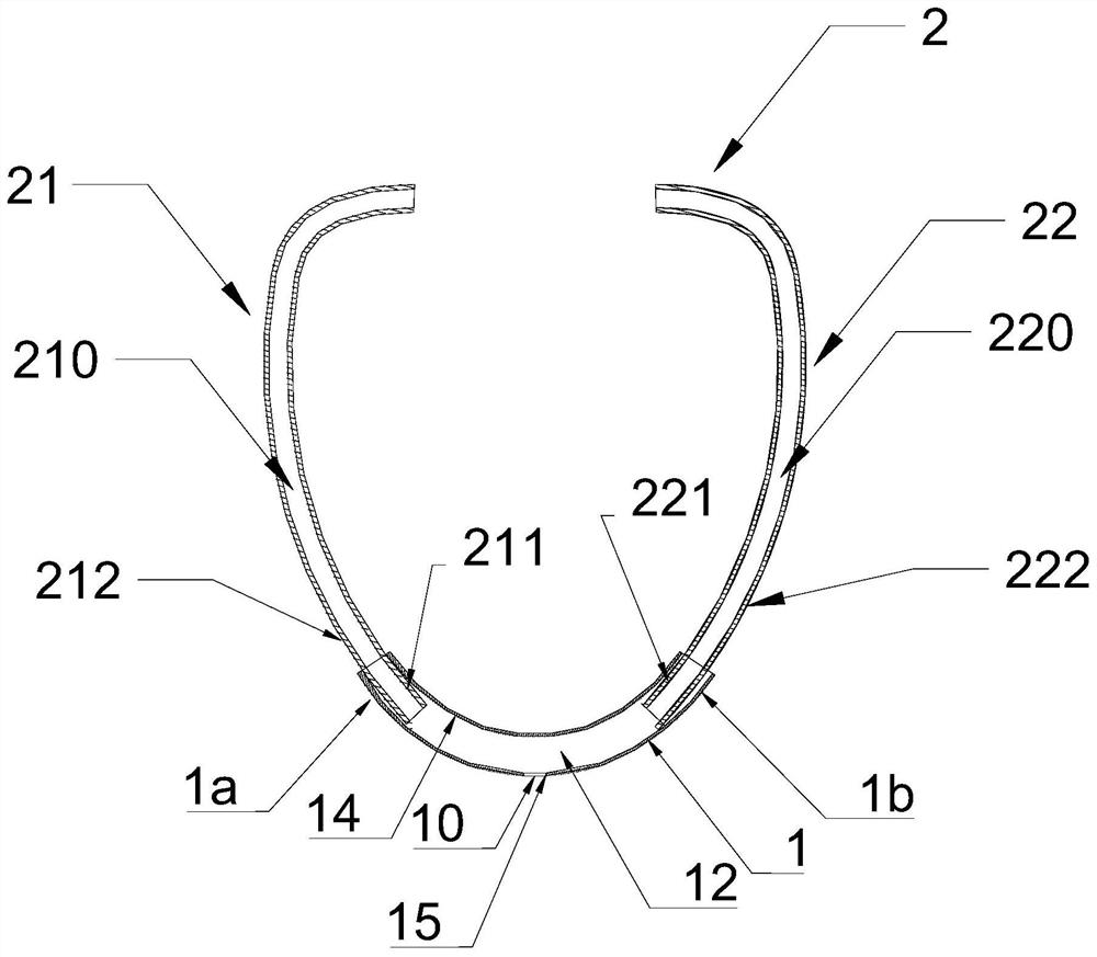
[0077] The earhook 2 includes a left earhook 21 and a right earhook 22 .
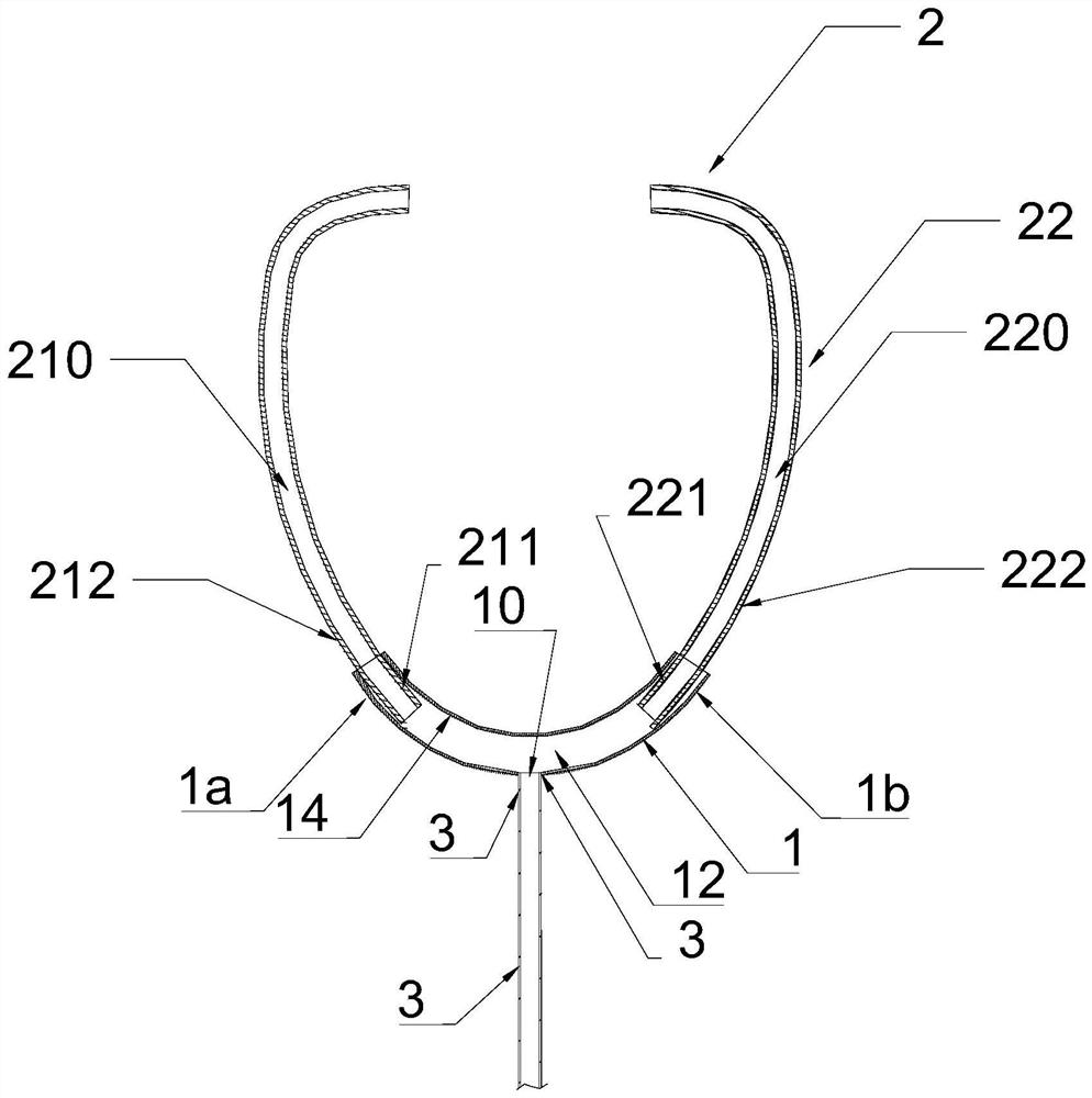
[0078] The connecting pipe 1 is used for connecting the earhook 2 and the sound guiding rubber tube 3 .
[0079] The A end 1a of the connecting pipe 1 is sleeved on the left earhook outer wall 212 of the left earhook rubber hose end 211 of the left earhook 21 , and the B end 1b of the connecting pipe 1 is sleeved on the right earhook rubber hose end 221 of the right earhook 22 on the outer wall 222 of the right ear. The lumen 210 of the left earhook communicates ...
Embodiment 2
[0082] combined with figure 1 , Figure 5 , Figure 6 , Figure 8 , Figure 10 , Figure 11 Shown, the present invention is described further.
[0083] The earhook hose connection assembly for the stethoscope includes earhook 2, connecting tube 1, earhook shrapnel 5, connector 6 and sound guide hose 3.
[0084] The earhook 2 includes a left earhook 21 and a right earhook 22 .
[0085]The earhook shrapnel 5 is fixed on the earhook 2 , the A end 5a of the earhook shrapnel 5 is fixed on the outer wall 212 of the left earhook, and the B end 5b is fixed on the outer wall 222 of the left earhook.
[0086] The connecting pipe 1 is a flexible, straight hollow rubber hose. The connecting pipe 1 is provided with a terminal 1a and a terminal B 1b at both ends. The middle part of the connecting pipe 1 is provided with a hole 10 passing through the pipe wall 11 on one side.
[0087] The earhook shrapnel 5 is penetrated in the lumen 12 of the connecting tube 1. No matter how the e...
PUM
Abstract
The invention relates to a connecting structure between an ear hook and a sound guide rubber tube of a stethoscope, in particular to a connecting tube for connecting the ear hook and the sound guide rubber tube and an ear hook rubber tube connecting assembly. According to the connecting tube for the stethoscope, the connecting tube is used for connecting the ear hook with the sound guide rubber tube, and the connecting tube ensures communication between an ear hook tube cavity and a sound guide rubber tube cavity. The connecting tube is a flexible straight hollow rubber tube; the two ends of the connecting tube are arranged at the two ends of the ear hook in a sleeving mode; a hole penetrating through the single-side tube wall is formed in the middle of the connecting tube; and the hole isused for enabling the tube cavity of the connecting tube to communicate with the tube cavity of the sound guide rubber tube. The connecting tube has the advantages of being small in size, convenientto carry, low in cost, high in percent of pass, free of flashes in the tube cavity wall of the sound guide rubber tube, smooth in tube cavity sound guide and balanced and clear in listening.
Description
technical field [0001] The invention relates to a connection structure between an earhook and a sound-guiding rubber hose of a stethoscope, in particular to a connecting pipe and an earhook rubber hose connecting assembly for connecting the earhook and the sound-guiding rubber hose. Background technique [0002] In the prior art, the earhook of the stethoscope is directly connected to the sound-guiding rubber hose, and the sound-guiding rubber hose is Y-shaped or U-shaped, and the two ends of the Y-shaped or U-shaped sound-guiding rubber hose are directly socketed on the earhook (the left earhook on the left earhook hose end of the right earhook and the right earhook hose end of the right earhook). [0003] However, no matter the sound-guiding hose is prepared by dipping or injection molding, due to the special shape of the sound-guiding hose, the mold core for producing the sound-guiding hose can only be spliced in splits to ensure that the mold core can be taken out of...
Claims
Application Information
Patent Timeline
Application Date:The date an application was filed.
Publication Date:The date a patent or application was officially published.
First Publication Date:The earliest publication date of a patent with the same application number.
Issue Date:Publication date of the patent grant document.
PCT Entry Date:The Entry date of PCT National Phase.
Estimated Expiry Date:The statutory expiry date of a patent right according to the Patent Law, and it is the longest term of protection that the patent right can achieve without the termination of the patent right due to other reasons(Term extension factor has been taken into account ).
Invalid Date:Actual expiry date is based on effective date or publication date of legal transaction data of invalid patent.

