Dynamic-adaptive vapor reduction system and method

a vapor reduction and dynamic technology, applied in water supply installations, instruments, specific gravity measurements, etc., can solve the problems of reducing affecting the accuracy of mass flow measurements and other measurements, and correspondingly reducing measurement accuracy

Active Publication Date: 2011-09-15
MEASUREMENT TECH GRP INC
View PDF21 Cites 13 Cited by
  • Summary
  • Abstract
  • Description
  • Claims
  • Application Information

AI Technical Summary

Benefits of technology

[0010]In an exemplary configuration, a fluid flow measurement system and methodology that reduces the presence of a vapor in a fluid being measured in a mass flow meter is provided.
[0011]In accordance with aspects of certain embodiments of the present disclosure, control flow valves are used to provide back pressure to prevent LCG from flashing while flowing in a mass flow meter.
[0014]One exemplary embodiment of the present disclosure is directed to a fluid flow measurement system. The system includes a mass flow meter configured to measure at least one parameter of a fluid flowing in the mass flow meter and a control valve located downstream of the mass flow meter. The control valve provides a back pressure on the fluid flowing in the mass flow meter. The system further includes a controller configured to detect a vapor in the fluid flowing in the mass flow meter. The controller adjusts the control valve in response to detecting the vapor in the fluid so as to reduce the vapor in the fluid flowing in the mass flow meter.
[0017]In yet another variation of such exemplary embodiment, the controller may adjust the control valve to provide a back pressure sufficient to prevent the fluid flowing in the mass flow meter from flashing. In still another variation of such exemplary embodiment, the controller may adjust the control valve to provide a maximum flow rate with enough back pressure to prevent the fluid flowing in the mass flow meter from flashing.
[0019]Another exemplary embodiment of the present disclosure is directed to a method of reducing the amount of vapor in a fluid flowing in a mass flow meter. The method includes flowing a fluid into a mass flow meter; measuring at least one parameter of the fluid at the mass flow meter; detecting a vapor in the fluid flowing in the mass flow meter; and adjusting a control valve located downstream of the mass flow meter in response to detecting a vapor in the fluid flowing in the mass flow meter such that the amount of vapor in the fluid flowing in the mass flow meter is reduced.

Problems solved by technology

The presence of a mixture of a vapor and a liquid in certain mass flow meters, such as Coriolis mass flow meters, can detrimentally affect the accuracy of the mass flow measurements and other measurements.
For example, the mixture of gas and liquid in the fluid flowing in a Coriolis mass flow meter causes a decrease in the amplitude of vibration and a corresponding decrease in measurement accuracy.
Error in density measurements is another detrimental effect of the presence of gas in fluid flow measurements.
If such density measurement is used to convert measured mass to volume, the calculated volume could have a significant error when compared to calibrated volumetric references.
Vapor eliminator tanks can be used to trap some of the vapor originating before the eliminator tanks, but do not typically control vapor forming after the eliminator due to critical pressure drops.
Another approach uses differential pressure valves to control line pressure, but the settings on the differential pressure valves are limited to a particular product with a particular vapor pressure.
Such can be a technically effective alternative, but requires expensive equipment and extensive support.
However, this method requires extra piping for the recirculation path.
While various methodologies have been developed for reducing detrimental effects caused by the presence of vapor in fluid flow measurement systems, no design has emerged that generally encompasses all of the desired characteristics, in an adaptive and dynamic form, as hereafter presented in accordance with the subject technology.

Method used


Image

  • Dynamic-adaptive vapor reduction system and method
  • Dynamic-adaptive vapor reduction system and method
  • Dynamic-adaptive vapor reduction system and method

Examples


Embodiment Construction

[0037]Reference now will be made in detail to embodiments of the present subject matter, one or more examples of which are illustrated in the drawings. Each example is provided by way of explanation of the present subject matter, not limitation of the present subject matter. In fact, it will be apparent to those skilled in the art that various modifications and variations can be made in the present subject matter without departing from the scope or spirit of the present subject matter. For instance, features illustrated or described as part of one embodiment, can be used with another embodiment to yield a still further embodiment. Thus, it is intended that the present subject matter encompass such modifications and variations as come within the scope of the appended claims and their equivalents.

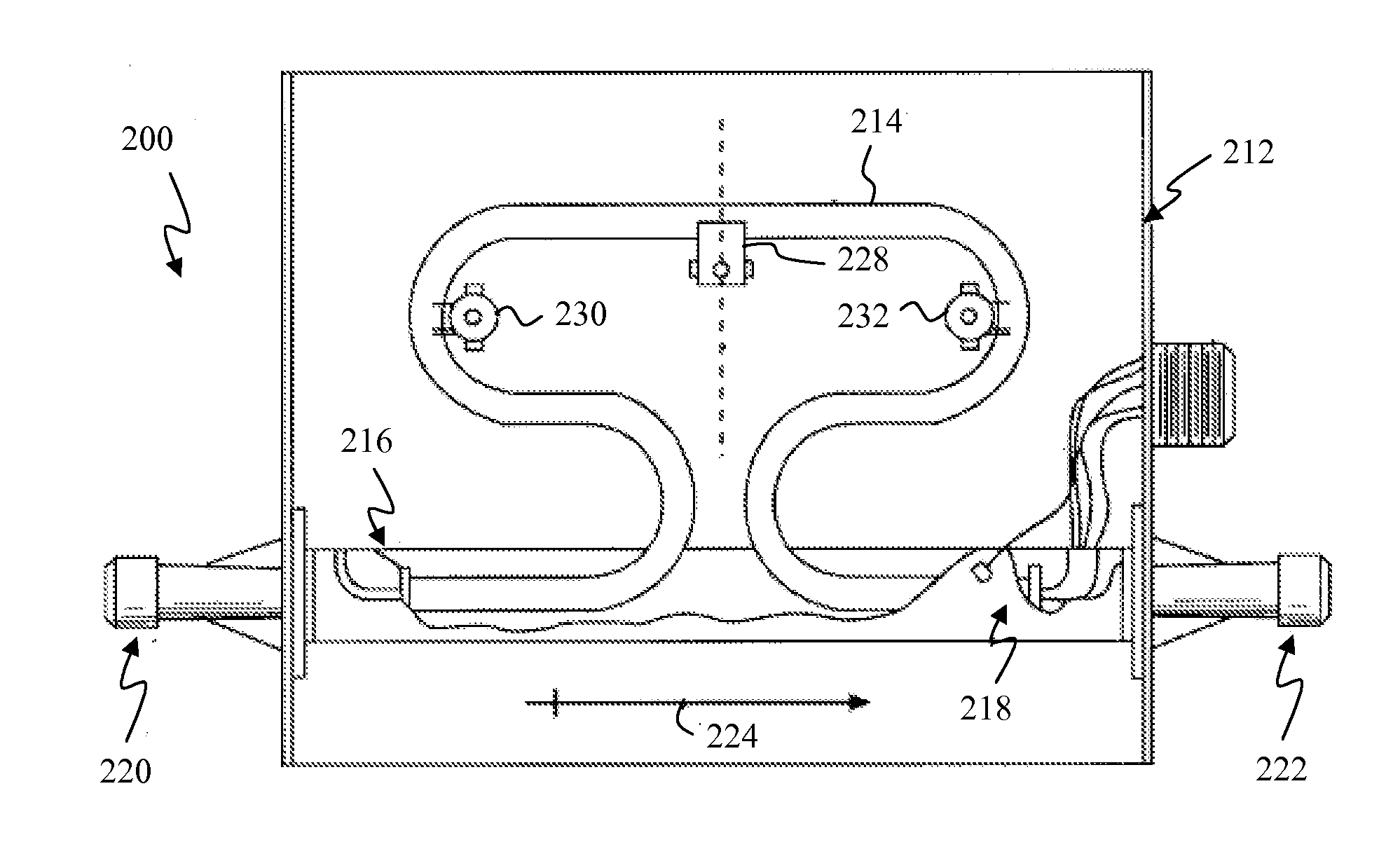
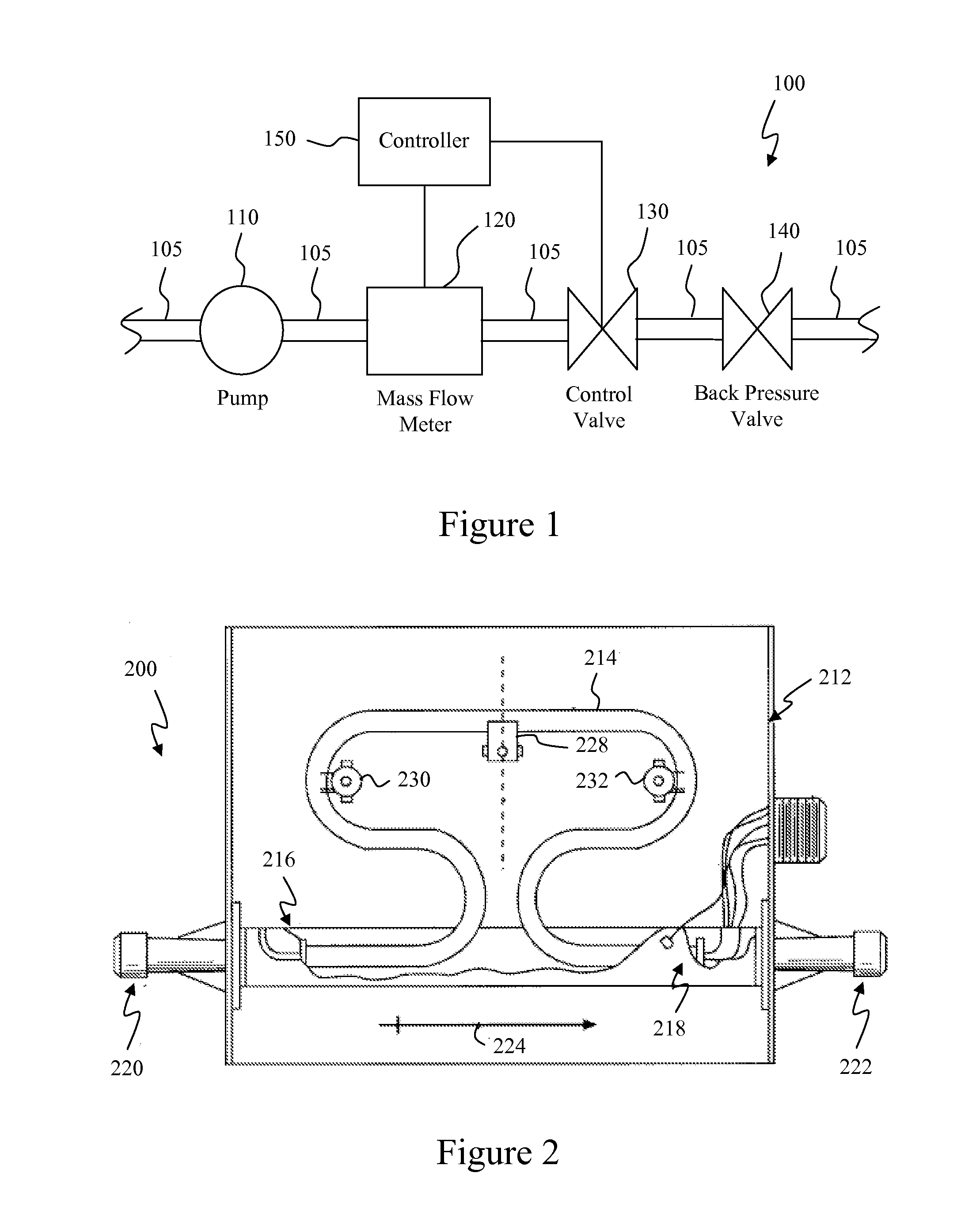
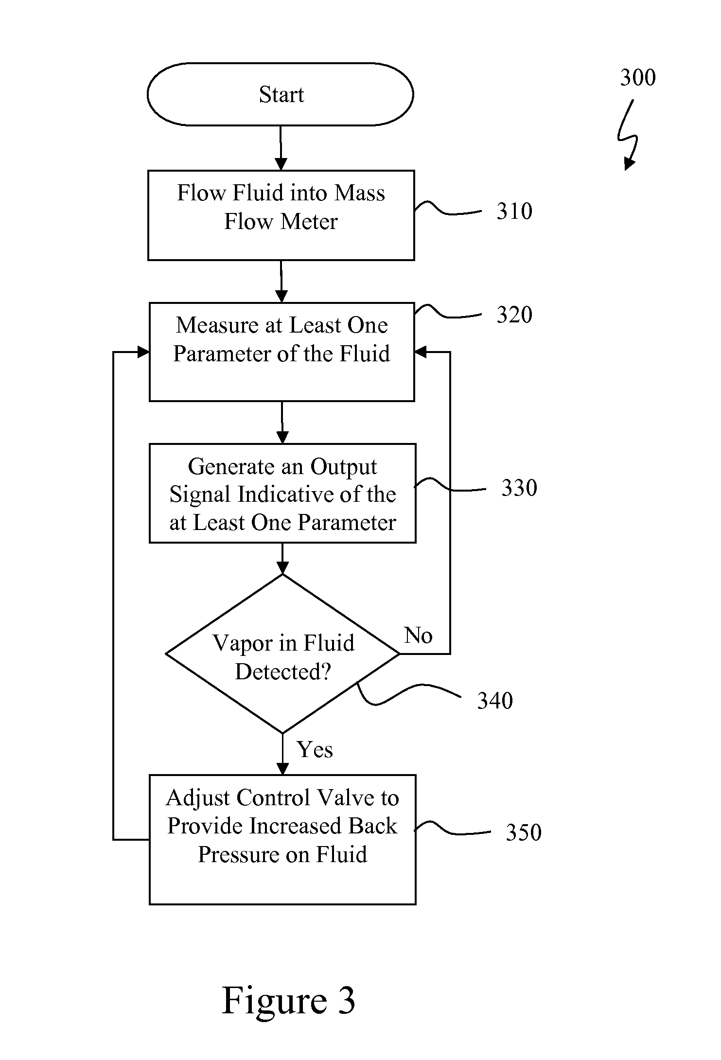
[0038]In general, the present technology provides for improved flow measurements for LCG, such as LPG. Embodiments of the present technology detect the presence of a vapor in a fluid flowing ...


PUM


Abstract

A system and method for improved flow measurements for LCG, such as liquid petroleum gas (LPG), is disclosed. Embodiments of the present technology detect the presence of a vapor in a fluid flowing in a mass flow meter. A control valve is then adjusted to provide enough back pressure to prevent the measured liquid from flashing and to reduce the presence of vapor in the fluid flowing in the mass flow meter. By keeping the fluid in liquid form, the present technology reduces the vapor flowing in the mass flow meter, increasing the accuracy of mass flow and other measurements. Utilizing a similar principle of vapor detection, embodiments of the present technology provide for improved average parameter value calculation, such as average density calculations and equivalent liquid volume calculations.

Description

FIELD OF THE INVENTION[0001]The present technology generally relates to fluid flow measurement systems and more particularly to reducing the presence of vapor and its detrimental effects in a fluid during flow measurements performed by a mass flow meter. The methods discussed hereon are not fluid dependent, but vapor-presence dependent; therefore, the methods apply to all liquefied compressed gases (LCG).BACKGROUND OF THE INVENTION[0002]Performing fluid flow measurements for LCG, such as liquid petroleum gas (LPG), entails a broader set of challenges that are not present in the measurement of other fluids. For the product to remain in a liquid state, LCG require the pressure of the fluid system to be maintained above the vapor pressure (i.e., the pressure at which a liquid-gas equilibrium occurs) for the fluid. If the pressure in the fluid system drops below the characteristic vapor pressure of the product, the liquid flashes (evaporates) to its vapor or gaseous state.[0003]The pres...

Claims


Application Information

Patent Timeline
Patent Type & Authority Applications(United States)
IPC IPC(8): F17D3/00G01F1/84F16K31/12
CPCG01F1/8413G01F1/8472G01F15/001G01N9/32G01F15/02G01F15/026G01N9/002G01F15/005Y10T137/0335Y10T137/7759F17D1/005F17D1/20
Inventor CABRERA, RAFAEL A.SANCHEZ, JAIME
Owner MEASUREMENT TECH GRP INC
Why Eureka
Try Eureka