
Wheelchair for upper and lower limb medical rehabilitation

A medical and wheelchair technology, applied in medical transportation, physiotherapy, passive exercise equipment, etc., can solve problems such as the inability to exercise the upper and lower limbs at the same time, the slow recovery efficiency of patients, and the lack of rehabilitation training. The wound is torn, and the effect is good

Active Publication Date: 2020-12-04
赵巍然
View PDF14 Cites 3 Cited by
  • Summary
  • Abstract
  • Description
  • Claims
  • Application Information

AI Technical Summary

Problems solved by technology

[0004] The invention proposes a wheelchair for medical rehabilitation of upper and lower limbs, which solves the problem of the current wheelchair, which has a single function and can only be used for riding when the patient's limbs do not let go of the stool. In addition, the upper and lower limbs cannot be exercised at the same time, and can only be trained and recovered separately one by one, which makes the recovery efficiency of patients slower.

Method used


Image

  • Wheelchair for upper and lower limb medical rehabilitation
  • Wheelchair for upper and lower limb medical rehabilitation
  • Wheelchair for upper and lower limb medical rehabilitation

Examples


Embodiment 1

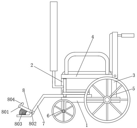
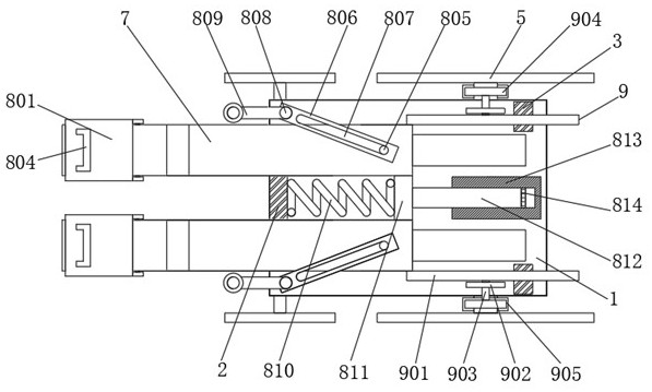
[0024] refer to Figure 1-3 , a wheelchair for upper and lower extremity medical rehabilitation, comprising a movable seat 1, a support rod 1 is fixed on one side of the top of the movable seat 1, and two symmetrical support rods 2 3 are fixed on the other side, and two support rods 2 3 are fixed on the other side. The same seat plate 4 is fixed on the top of the support rod one 2, and the two side walls of the moving seat 1 are all rotatably connected with a rotating shaft one, and the outer sides of the two rotating shafts one are fixedly sleeved with a wheel body one 5, and the two sides of the moving seat 1 The side walls are all rotatably connected with rotating shafts 2, and the outer sides of the two rotating shafts 2 are fixedly sleeved with wheel body 2 6, and the top of the moving seat 1 is slidably connected with two relatively symmetrical movable pedals 7, and the two movable pedals 7 are respectively located on the support Both sides of rod one 2.

[0025] The mo...

Embodiment 2

[0027] refer to Figure 1-3 , the training mechanism 8 is connected between the two movable pedals 7, the mobile seat 1 and the seat board 4, and the training mechanism 8 includes hinged blocks 802 respectively connected to the two side walls of the two movable pedals 7, and on the same movable pedal 7 A pedal 801 is fixed between the two hinged blocks 802, and the end of the pedal 801 facing the movable pedal 7 has a circular arc surface structure, and a wave-shaped telescopic air bag is fixed between the bottom of the pedal 801 and the upper surface of the movable pedal 7 803, the top of the pedal 801 is fixed with a silicone foot cover 804 with an n-type vertical section, and the tops of the two movable pedals 7 are respectively fixed with a limit column 805 with different lengths, and the outer sides of the two limit columns 805 are respectively movable sleeves A rotating plate 806 is provided, and two rotating plates 806 are arranged in a staggered manner. The inside of t...

Embodiment 3

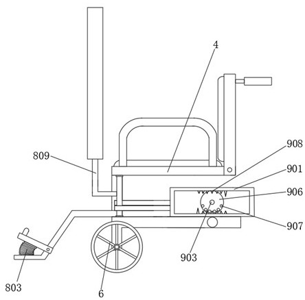
[0030] refer to Figure 2-3A transmission mechanism 9 is connected between the two movable pedals 7, the moving seat 1 and the two rotating shafts. The transmission mechanism 9 includes a movable frame 901 fixed on the side wall of the movable pedal 7, and the movable frame 901 is slidably connected to the movable seat 1. The top, the top of the moving seat 1 is fixed with a support block 902, the inner rotation of the support block 902 is connected with a connecting shaft 903, one end of the connecting shaft 903 is fixed with a gear 904, and the other end is fixed with a turntable 906, and the surface of the turntable 906 is circumferential. A plurality of guide posts 907 are distributed, gear two 905 is meshed and connected to the bottom of gear one 904, and gear two 905 is fixedly sleeved on the outside of rotating shaft one. With the matched pin teeth 908, the inside of the support rod 2 3 is provided with a movable channel matched with the movable frame 901.

[0031] The...


PUM


Abstract

The invention belongs to the technical field of wheelchairs, particularly relates to a wheelchair for upper and lower limb medical rehabilitation, and aims at solving the problems that an existing wheelchair is single in function, can only meet the sitting requirement when the limbs of a patient are inconvenient, does not have the function of facilitating rehabilitation training of the patient inthe sitting process, is poor in using effect and cannot exercise the upper and lower limbs simultaneously; and training rehabilitation can only be carried out in a one-to-one separation mode, so thatthe rehabilitation efficiency of the patient is relatively low. According to the scheme, the wheelchair comprises a movable base; a first supporting rod is fixed to one side of the top of the movablebase, two symmetrical second supporting rods are fixed to the other side of the top of the movable base, and the same seat plate is fixed to the tops of the two second supporting rods and the top of the first supporting rod. By means of a training mechanism, a patient can sit on the device conveniently, meanwhile, the function of conducting rehabilitation training on the upper limb and the lower limb of the patient at the same time in the sitting process can be achieved, the using effect is relatively good, and the rehabilitation efficiency of the patient is greatly improved.

Description

technical field [0001] The invention relates to the technical field of wheelchairs, in particular to a wheelchair for medical rehabilitation of upper and lower limbs. Background technique [0002] The wheelchair is an important tool for rehabilitation. It is not only a means of transportation for the physically disabled, but more importantly, it enables them to perform physical exercises and participate in social activities with the help of wheelchairs. Ordinary wheelchairs generally consist of a wheelchair frame, wheels, brakes and four seats. Partial composition. [0003] The current wheelchair has a single function, which can only be satisfied with the patient's limbs when he or she does not let go of the stool. It does not have the function of allowing the patient to carry out rehabilitation training during the ride, and the use effect is poor. In addition, the upper and lower limbs cannot be exercised at the same time. , can only carry out training rehabilitation one b...

Claims


Application Information

Patent Timeline
Patent Type & Authority Applications(China)
IPC IPC(8): A61G5/00A61G5/10A61G5/12A61H1/02
CPCA61G5/00A61G5/10A61G5/128A61H1/0274A61H1/0237A61H1/0266A61H2201/0149A61H2205/06A61H2205/10A61H2205/12
Inventor 赵巍然刘静赵骏腾
Owner 赵巍然
Learn More