Workpiece cleaning device for machining

A cleaning device and mechanical processing technology, which is applied in the field of mechanical processing, can solve the problems of workpiece processing influence, impurity cleaning, etc.

Inactive Publication Date: 2020-12-04
佘巧
View PDF1 Cites 6 Cited by
  • Summary
  • Abstract
  • Description
  • Claims
  • Application Information

AI Technical Summary

Problems solved by technology

A new type of workpiece cleaning device in the above-mentioned patent has the following disadvantages: when cleaning a spherical workpiece, the imp

Method used


Image

  • Workpiece cleaning device for machining
  • Workpiece cleaning device for machining
  • Workpiece cleaning device for machining

Examples


Embodiment 1

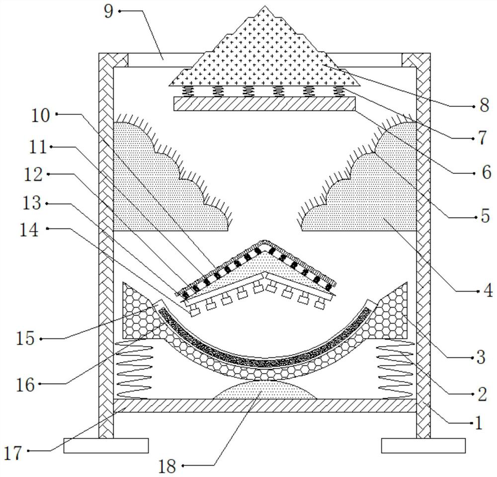
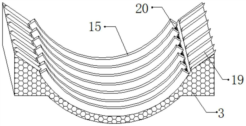
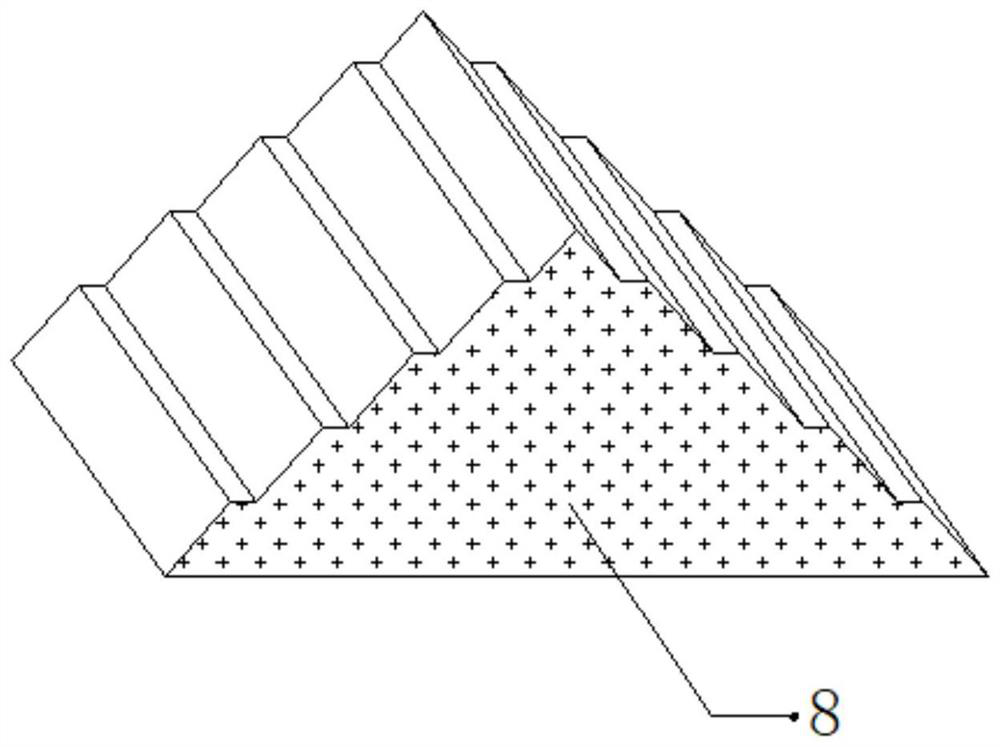
[0029] refer to Figure 1-3 , a workpiece cleaning device for mechanical processing, comprising a fixed frame 1, the top outer wall of the fixed frame 1 is provided with a feed port 9, and a fixed plate 17 is connected by bolts between the opposite inner walls of the fixed frame 1, and the fixed plate 17 Both sides of the top outer wall are connected with the first spring 2 by bolts, and the top outer walls of the two first springs 2 are connected with the filter plate 3 by bolts, and the shape of the filter plate 3 is arc-shaped, and the top outer wall of the filter plate 3 A plurality of partitions 15 are connected by bolts, and the outer walls of both sides of the partitions 15 are connected with cleaning brushes 16 by bolts, and the top outer wall of the filter plate 3 is connected with a plurality of brush plates 20 by bolts, and the brush plates 20 are located adjacent to each other. Between the two partitions 15, the top outer wall of the fixed plate 17 is connected wit...

Embodiment 2

[0039] refer to Figure 4 , a workpiece cleaning device for mechanical processing. Compared with Embodiment 1, the outer walls of both sides of the fixed frame 1 are connected with connecting plates 21 through hinges, and the outer walls of one side of the two connecting plates 21 are bolted with suspension wires. 22. The outer wall of the bottom of the suspension wire 22 is bolted with an impact block 23, and a third spring 24 is connected between the connecting plate 21 and the fixed frame 1 through bolts, which can cause the impact block 23 to collide with the device through the vibration generated during cleaning. Therefore, the vibration generated by the collision is used to process the dust and debris adhering to the device, preventing the dust and debris from adhering to the inner wall of the device and interfering with the cleaning of the workpiece.

[0040] Working principle: when in use, place the spherical workpiece that needs to be cleaned on the device through the...


PUM


Abstract

The invention discloses a workpiece cleaning device for machining. The workpiece cleaning device comprises a fixing frame, wherein a feeding port is formed in the outer wall of the top of the fixing frame, fixing plates are fixedly connected between the inner walls of the two opposite sides of the fixing frame, first springs are fixedly connected to the two sides of the outer walls of the tops ofthe fixing plates, the outer walls of the tops of the two first springs are fixedly connected with filter plates, the filter plates are arc-shaped, a plurality of partition plates are fixedly connected to the outer walls of the tops of the filter plates, cleaning brushes are fixedly connected to the outer walls of the two sides of the partition plates, a plurality of brush plates are fixedly connected to the outer walls of the tops of the filter plates, and the brush plates are located between every two adjacent partition plates. According to the workpiece cleaning device, the surface of a workpiece can be prevented from being abraded due to collision of two adjacent workpieces during rolling, the situation that the workpiece cleaning device cannot effectively clean the workpiece due to the fact that the rolling speed of a spherical workpiece is relatively fast can be prevented, and the situation that dust and chippings adhere to the inner wall of the workpiece cleaning device to interfere with the cleaning of the workpiece can be prevented.

Description

technical field [0001] The invention relates to the technical field of mechanical processing, in particular to a workpiece cleaning device for mechanical processing. Background technique [0002] During the production process of the workpiece, the workpiece needs to be cleaned. It is relatively easy to clean the general workpiece. However, when cleaning the spherical workpiece, the rolling of the spherical workpiece may affect the cleaning of the workpiece. [0003] After retrieval, the Chinese patent authorization number is the patent of CN107363015A, which discloses a novel workpiece cleaning device. The novel workpiece cleaning device includes a bottom plate, a motor one, a water return tank and a spray block, and the water return tank is fixed on the bottom plate through supporting legs. The invention designs a new type of workpiece cleaning device in which the motor can push the workpiece on the workpiece runner forward through the driven transmission belt and the driv...

Claims


Application Information

Patent Timeline
IPC IPC(8): B08B7/02B08B3/02B08B13/00B07B1/28
CPCB07B1/28B08B3/02B08B7/02B08B13/00
Inventor 佘巧
Owner 佘巧
Why Eureka
Try Eureka