Multifunctional bar machining treatment device
A processing device and multi-functional technology, which is used in metal processing, devices for applying liquid to the surface, coatings, etc. Anti-vibration effect
- Summary
- Abstract
- Description
- Claims
- Application Information
AI Technical Summary
Problems solved by technology
Method used
Image

Examples
specific Embodiment approach 1
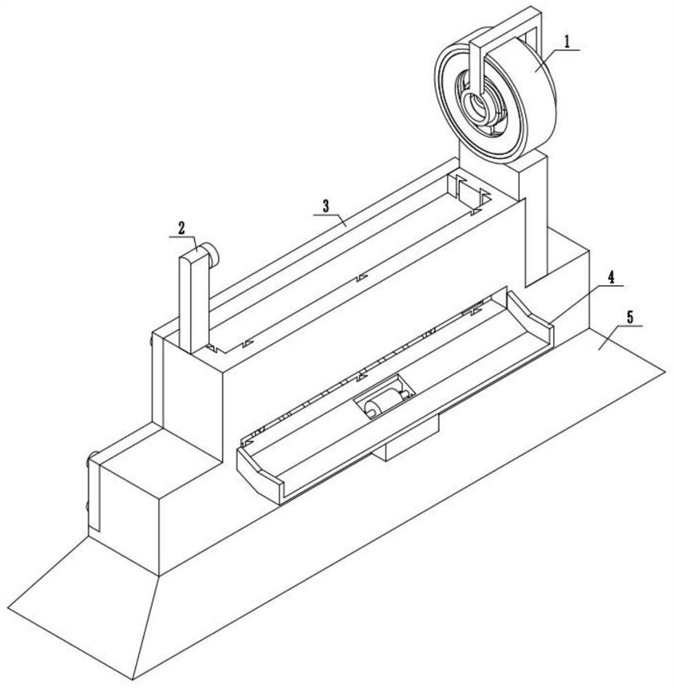
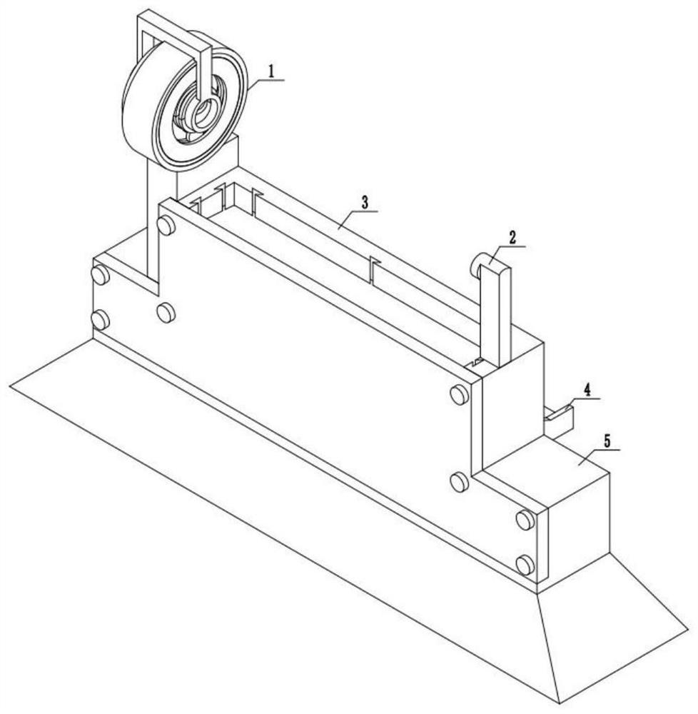
[0046] Combine below figure 1 , 2 Describe this embodiment, a multifunctional rod processing device, including a rod cutting device 1, a rod length limit frame 2, a rod conveying device 3, a rod marking device 4 and a fixed base 5, the described The bar cutting processing device 1 is fixedly installed above the bar conveying device 3, the bar length limit frame 2 is fixedly installed above the bar conveying device 3, and the bar marking device 4 is fixedly installed on the bar conveying device 3, The top of the fixed base 5 is fixedly installed with a rod conveying device 3 .
specific Embodiment approach 2
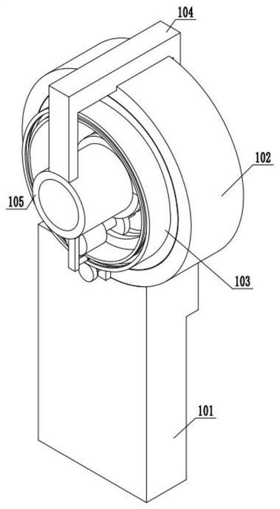
[0048] Combine below image 3 , 4 , 5, 6, 7, 8, 9, and 10 illustrate this embodiment, and this embodiment will further describe Embodiment 1. The described rod cutting processing device 1 includes a fixed bracket 101, a fixed overcoat 102, a cutting device 103, a fixed Frame body 104, fixed sleeve body 105, fixed overcoat 102 is fixedly installed on the top of fixed bracket 101, cutting device 103 is installed in the fixed overcoat 102, fixed frame body 104 is fixedly installed on the fixed overcoat 102, fixed frame body 104 is fixedly installed with The fixed sleeve body 105, the fixed sleeve body 105 is fixedly installed on the cutting device 103;
[0049] The cutting device 103 includes a driving device 106 and a cutting device body 107, and the driving device 106 is fixedly installed on the cutting device body 107;
[0050] Described driving device 106 comprises sliding groove A108, driving ring gear A109, sliding frame 110, power motor A111, and sliding groove A108 is a...
specific Embodiment approach 3
[0053] Combine below Figure 11 , 12 , 13, 14, and 15 illustrate this embodiment, and this embodiment will further explain Embodiment 1. The bar material conveying device 3 includes a conveying device body 301, a baffle plate 302, a fastening screw 303, and the conveying device body 301 and the baffle plate The plates 302 are in contact, and the baffle plate 302 is installed on the conveyor body 301 by fastening screws 303;
[0054] The transmission device body 301 includes a fixed outer shell 304, a trapezoidal sliding groove 305, a transmission plate 306, a connection block A307, a push rod 308, a connection block B309, a push sleeve 310, a slide rod 311, a return spring 312, an adjustment screw 313, Adjusting nut 314, jacking rod 315, bar outlet 316, and trapezoidal sliding groove 305 are arranged on the fixed outer shell 304, and a plurality of trapezoidal sliders are arranged on the transmission plate 306, and are installed in the trapezoidal sliding groove 305 by slidin...
PUM
 Abstract
Description
Claims
Application Information
 - R&D
- Intellectual Property
- Life Sciences
- Materials
- Tech Scout
- Unparalleled Data Quality
- Higher Quality Content
- 60% Fewer Hallucinations
Browse by: Latest US Patents, China's latest patents, Technical Efficacy Thesaurus, Application Domain, Technology Topic, Popular Technical Reports.
© 2025 PatSnap. All rights reserved.Legal|Privacy policy|Modern Slavery Act Transparency Statement|Sitemap|About US| Contact US: help@patsnap.com