Unmanned aerial vehicle rotor wing and rotor wing protection frame

A technology of a rotor and a protective frame, applied in the field of drones, can solve the problems of inconvenient drone flight performance, breakage, and inability to adjust the tilt angle of the drone's rotor.

Inactive Publication Date: 2020-12-04
安徽晟东科技有限公司
View PDF6 Cites 0 Cited by
  • Summary
  • Abstract
  • Description
  • Claims
  • Application Information

AI Technical Summary

Problems solved by technology

[0005] The purpose of the present invention is to provide a UAV rotor and a rotor protection frame to solve the problem of inability to adjust the inclination angle of the UAV rotor proposed in the above background technology, so that the adaptability of the UAV rotor cannot be adjusted according to the wind force. It is convenient to give full play to the flight performance of the UAV, but it cannot reduce the wind resistance on the surface of the UAV rotor, and cannot protect the UAV rotor. It is easily affected by the branches of plants, and when the drone is stored, its rotor is extremely vulnerable to being squeezed, resulting in breakage or bending deformation.

Method used


Image

  • Unmanned aerial vehicle rotor wing and rotor wing protection frame
  • Unmanned aerial vehicle rotor wing and rotor wing protection frame
  • Unmanned aerial vehicle rotor wing and rotor wing protection frame

Examples


Embodiment Construction

[0026] The following will clearly and completely describe the technical solutions in the embodiments of the present invention with reference to the accompanying drawings in the embodiments of the present invention. Obviously, the described embodiments are only some, not all, embodiments of the present invention. Based on the embodiments of the present invention, all other embodiments obtained by persons of ordinary skill in the art without making creative efforts belong to the protection scope of the present invention.

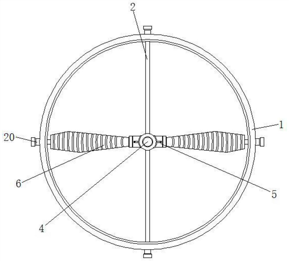
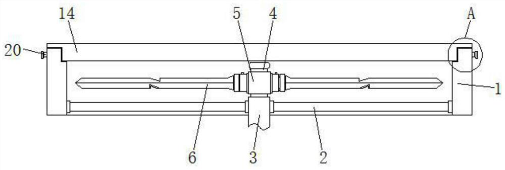
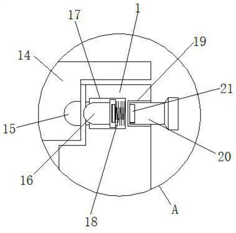
[0027] see Figure 1-6 , the present invention provides a technical solution: a UAV rotor and rotor protection frame, including a protection frame 1, a motor rotor 4, a UAV rotor 6 and a magnet 21, and a support rod 2 is installed on the inside of the protection frame 1 , and a support sleeve 3 is installed on the support rod 2, and the support sleeve 3 is connected to the protective frame 1 through the support rod 2. The inside of the support sleeve 3 is prov...


PUM


Abstract

The invention discloses an unmanned aerial vehicle rotor wing and rotor wing protection frame comprising a protection frame body, a motor rotor, an unmanned aerial vehicle rotor wing and a magnet; a support rod is installed on the inner side of the protection frame body, a supporting sleeve is installed on the support rod, the supporting sleeve is connected with the protection frame body through the support rod, and an ejector rod is arranged on the inner side of a groove hole. And the ejector rod is connected with the protection frame body through a slotted hole, and magnets are installed onthe ejector rod and a positioning rod correspondingly. According to the unmanned aerial vehicle rotor wing and rotor wing protection frame, the unmanned aerial vehicle rotor wing can be manually screwed to rotate on the mounting sleeve through a butt joint rod; at the moment, the rotating unmanned aerial vehicle rotor wing can conveniently conduct angle rotation adjustment; and after the unmannedaerial vehicle rotor wing finishes rotating, a reset spring can push an adjusting lantern ring to extend out of the storage groove; the adjusting lantern ring can conveniently drive the limiting inserting rod to be inserted into the limiting inserting groove in the surface of the unmanned aerial vehicle rotor wing to fix the angle of the unmanned aerial vehicle rotor wing completing angle rotation.

Description

technical field [0001] The invention relates to the technical field of unmanned aerial vehicles, in particular to an unmanned aerial vehicle rotor and a rotor protection frame. Background technique [0002] Unmanned aircraft, commonly known as: unmanned aircraft, unmanned aerial vehicle, unmanned aerial vehicle, unmanned combat aircraft, bee-type aircraft; in a broad sense, it refers to various remote-controlled aircraft that do not require a driver to board and drive, and generally refers to military aircraft. Fang's unmanned reconnaissance aircraft and civilian small remote-controlled drones. Civilian drones are mostly used for aerial photography and agricultural plant protection work. They are a relatively common flying tool, but existing drones usually use The following problems exist: [0003] 1. It is impossible to adjust the tilt angle of the UAV rotor, so that the adaptability of the UAV rotor cannot be adjusted according to the wind force, and it is inconvenient to...

Claims


Application Information

Patent Timeline
Patent Type & Authority Applications(China)
IPC IPC(8): B64C27/00B64C27/32B64C27/14B64C39/02
CPCB64C27/006B64C27/32B64C27/14B64C39/02B64U30/20
Inventor 杨凯
Owner 安徽晟东科技有限公司
Why Eureka
Try Eureka