Combined plugging device for tunnel lining

A plugging device and a combined technology, which is applied in the direction of tunnel lining, tunnel lining, shaft lining, etc., can solve the problems of inconvenient tightness, large welding volume, hidden safety hazards, etc. The effect of easy operation

Pending Publication Date: 2020-12-04
HUNAN WUXIN TUNNEL INTELLIGENT EQUIP CO LTD
View PDF0 Cites 0 Cited by
  • Summary
  • Abstract
  • Description
  • Claims
  • Application Information

AI Technical Summary

Problems solved by technology

The structure of the steel mold + plugging piece plugging device is composed of upper plugging mold, lower plugging mold, wooden board of plugging mold, pressing parts of plugging parts, struts, strut seats, wedge-shaped wooden pins, etc. As follows: (1) Its structure is relatively complicated, and its installation and fixing are not safe; (2) The strut seat and the hinged ear plate of the lower plugging mold need to be fixed by welding on site, and the amount of welding on site is relatively large. The wooden board is fixed by the struts, the pressing parts of the blocking parts and the wedge-shaped wooden blocks. The struts need to be removed every time the mold is demoulded. Once the deformation occurs, the struts may not be removed, and the removed struts are free on site (3) The pressing part of the sealing part is welded on the upper sealing mold panel with a screw rod. This kind of fixing method is inconvenient and tight, and the sealing board needs to cut a gap to avoid the position of the screw rod; (4) The plugging structure of steel mold + plugging parts cannot adapt to different arc radii; (5) There are gaps between the left and right adjacent plugging molds, and it is easy to leak grout during lining

Method used


Image

  • Combined plugging device for tunnel lining
  • Combined plugging device for tunnel lining
  • Combined plugging device for tunnel lining

Examples


Embodiment 1

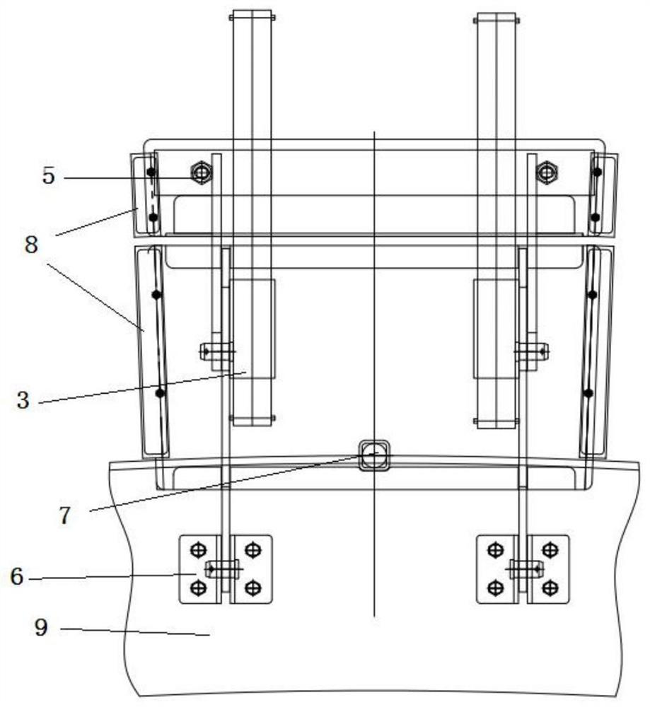
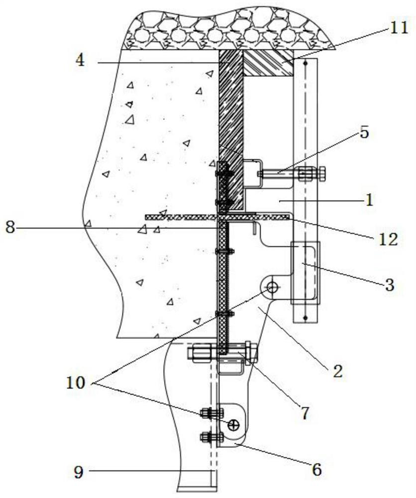
[0030] A combined sealing device for tunnel lining, its specific structure is as follows Figure 1-Figure 5 As shown, it mainly includes the upper plugging die 1, the lower plugging die 2 and the strut assembly 3, the details are as follows:

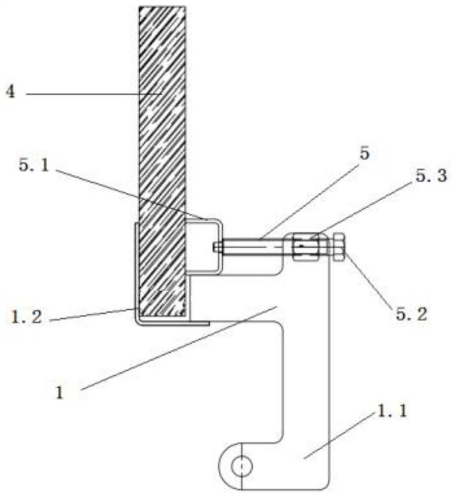
[0031] The upper plugging die 1 includes an upper plugging die hinge ear 1.1 and a mounting groove 1.2 for installing the plugging part 4, which facilitates the positioning and limiting of the plugging part 4 during installation. For details, see figure 2 and image 3 .

[0032] The lower plugging die 2 includes the lower plugging die hinge ear 2.1, the upper plugging die 1 and the lower plugging die 2 pass through the upper plugging die hinge ear 1.1, the lower plugging die hinge ear 2.1 and the connector 10 (such as a pin Shaft) is hinged, so that the upper plugging mold 1 can rotate and swing around the connecting piece 10 relative to the lower plugging mold 2, so as to realize the mold erecting and demoulding operations. The bloc...


PUM


Abstract

The invention discloses a combined plugging device for tunnel lining. The combined plugging device comprises at least one group of plugging single pieces, wherein each plugging single piece comprisesan upper plugging mold, a lower plugging mold and a support rod assembly; the upper plugging mold is movably arranged on the lower plugging mold; the support rod assembly comprises a support rod; thesupport rod is arranged on the lower plugging mold; and the combination of the upper plugging mold and the lower plugging mold or the combination of the upper plugging mold, the lower plugging mold and the plugging piece forms a lining surface matched with a position to be lined and a water stop piece. By using the scheme, the combined plugging device has the effects that the integral structure issimple; the combination of the upper plugging mold and the lower plugging mold or the combination of the upper plugging mold, the lower plugging mold and the plugging piece forms the lining surface matched with the position to be lined and the water stop piece, so that the lining construction is convenient; a sealing assembly is arranged on each plugging single piece and is used for eliminating agap between the plugging single pieces; and the sharing of the plugging molds with different circular arc cross sections is realized, so that the repeated use of the plugging molds is realized.

Description

technical field [0001] The invention relates to the technical field of tunnel construction, in particular to a combined sealing device for tunnel lining. Background technique [0002] With the extensive construction of tunnel engineering, the use of lining trolleys for the secondary lining of tunnels has been widely promoted, and the subsequent combined sealing device of steel formwork + sealing parts (such as wooden formwork) is also more and more widely used. The structure of the steel mold + plugging piece plugging device is composed of upper plugging mold, lower plugging mold, wooden board of plugging mold, pressing parts of plugging parts, struts, strut seats, wedge-shaped wooden pins, etc. As follows: (1) Its structure is relatively complicated, and its installation and fixing are not safe; (2) The strut seat and the hinged ear plate of the lower plugging mold need to be fixed by welding on site, and the amount of welding on site is relatively large. The wooden board ...

Claims


Application Information

Patent Timeline
IPC IPC(8): E21D11/10E21D11/38
CPCE21D11/10E21D11/102E21D11/38
Inventor 龚俊曾勇王慧民曾志其熊幸
Owner HUNAN WUXIN TUNNEL INTELLIGENT EQUIP CO LTD
Why Eureka
Try Eureka