
Tab, can lid, and method for manufacturing can lid

A technology of can lids and ring holes, which is applied in the field of manufacturing of pull rings, can lids and can lids, which can solve the problems of reduced opening performance and achieve the effect of simple structure

Active Publication Date: 2020-12-04
DAIWA CAN
View PDF19 Cites 0 Cited by
  • Summary
  • Abstract
  • Description
  • Claims
  • Application Information

AI Technical Summary

Problems solved by technology

[0004] However, when the tab is rotated in the circumferential direction so that the center of the tab deviates from the line passing through the rivet and the specified position within the score line, the force generated by the lever action cannot be used during the opening operation. Sufficient action on the score line may reduce the lid opening performance

Method used


Image

  • Tab, can lid, and method for manufacturing can lid
  • Tab, can lid, and method for manufacturing can lid
  • Tab, can lid, and method for manufacturing can lid

Examples


Embodiment Construction

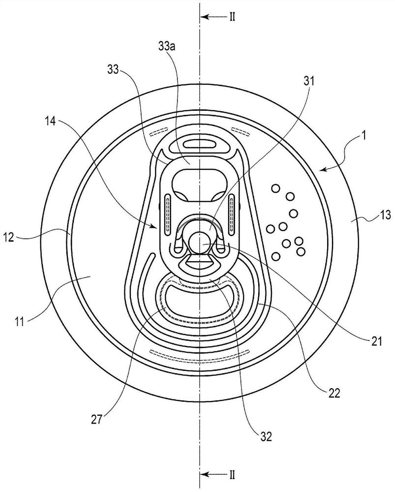
[0031] Below, use Figure 1 to Figure 9 The structure of the can end 1 having the tab 14 according to one embodiment of the present invention and the method of manufacturing the can end 1 will be described.

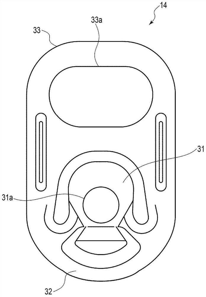
[0032] figure 1 It is a plan view showing the structure of the can lid 1 according to one embodiment of the present invention, figure 2 It is a sectional view showing the structure of the can lid 1 . image 3 as well as Figure 4 is a plan view showing the structure of the pull ring 14, image 3 Shown from the front side of the can lid 1, Figure 4 It is shown from the side of the panel portion 11 of the can lid 1 . Figure 5 It is a cross-sectional view showing a part of the tab 14 , that is, a structure of a material constituting the tab 14 . Figure 6 to Figure 8 It is an explanatory drawing which shows an example of each process of the manufacturing method of the can end 1, Figure 9 It is a flowchart showing an example of each step of the manufacturing method...


PUM


Abstract

This tab (14) used on a can lid (1) is formed of a metal plate (56) obtained by stacking a resin film (52) on at least one main surface of a base material (51) formed of a metal material, the metal plate comprising: an affixation part (31) including a rivet hole (31a) into which a rivet (21) formed in a panel section (11) of the can lid (1) is inserted; a pressing part (32) that is formed integrally with the affixation part (31) and presses the region inside a score line (22) formed in the panel section (11); and a hook part (33) formed integrally with the pressing part (32).

Description

technical field [0001] The invention relates to a pull ring used for a can container, a can lid and a method for manufacturing the can lid. Background technique [0002] Conventionally, as can lids for can containers for beverages and food, stay-on-tab type can lids in which opening operations are performed by a pull ring are used. Such a can lid has a structure in which a part of the panel is broken along the score line by lifting the finger hook portion of the tab fixed to the panel by a rivet to open the panel. [0003] Such a can lid fixes the tab to the panel portion by inserting a cylindrical rivet formed in the panel portion into a rivet hole formed in the tab and riveting the upper end of the rivet. Therefore, the tab is fixed to the panel portion so as to be rotatable in the circumferential direction around the rivet. [0004] However, when the tab is rotated in the circumferential direction so that the center of the tab deviates from the line passing through the ...

Claims


Application Information

Patent Timeline
Patent Type & Authority Applications(China)
IPC IPC(8): B65D17/32B21D51/44
CPCB21D51/44B21D51/383B65D17/4012B65D2517/0014B41M1/10B41M1/28B65D2517/0016B65D2517/5075
Inventor 大越俊幸八坂雅彦岛津真治岩丸忠义藤原博文
Owner DAIWA CAN
Learn More