
Manufacturing method of fuel cell assembly

A fuel cell, manufacturing method technology, applied in the direction of fuel cell components, fuel cells, final product manufacturing, etc.

Active Publication Date: 2020-06-23
HONDA MOTOR CO LTD
View PDF6 Cites 0 Cited by
  • Summary
  • Abstract
  • Description
  • Claims
  • Application Information

AI Technical Summary

Problems solved by technology

In this way, in the conventional technology, there is room for improvement in terms of more reliably preventing the generation of burrs.

Method used


Image

  • Manufacturing method of fuel cell assembly
  • Manufacturing method of fuel cell assembly
  • Manufacturing method of fuel cell assembly

Examples


Embodiment Construction

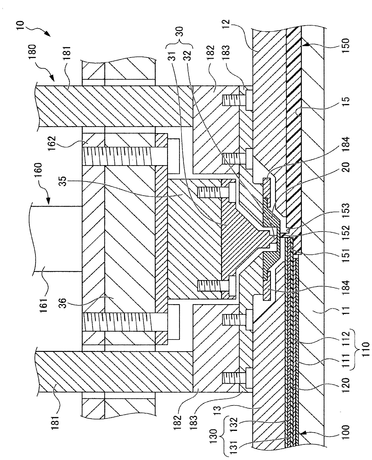
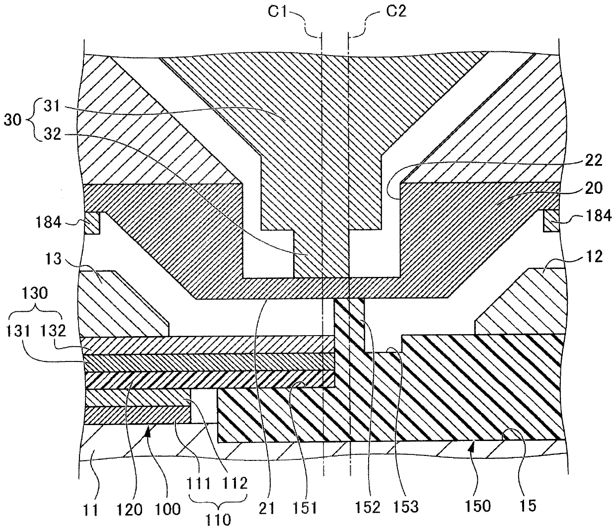
[0036] Hereinafter, a preferred embodiment of the present invention will be described with reference to the drawings. figure 1 It is a cross-sectional view schematically showing a joining device 10 according to an embodiment of the present invention. exist figure 1 The main parts of the joining device 10 are shown in . figure 2 It is an enlarged cross-sectional view showing the configuration of the heat transfer member 20 and the heating member 30 of the present embodiment.

[0037] Such as figure 1 As shown, the bonding apparatus 10 of the present embodiment includes a placing jig 11 , a frame pressing member 12 , a bonded body pressing member 13 , a heat transfer member 20 , and a heating member 30 .

[0038] The placing jig 11 has the electrolyte membrane-electrode assembly 100 and the resin frame 150 placed on its upper surface. A concave portion 15 for placing the resin frame 150 is formed on the placing jig 11 . The electrolyte membrane-electrode assembly 100 is pl...


PUM


Abstract

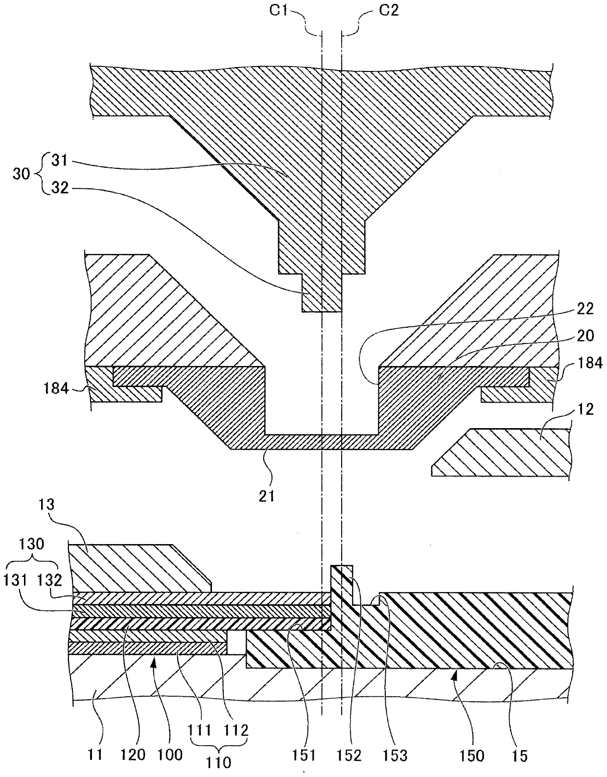
A method for manufacturing a fuel cell assembly includes: arranging an end face of a gas diffusion layer on a placement jig in a state abutting an end face of a resin frame; melting a part of the frame member and causing to penetrate into the gas diffusion layer by pressurizing the projecting part by way of a heat-transfer member, and heating the projecting part via the heat-transfer member by abutting a heating member against of the heat-transfer member; and solidifying the part of the resin frame having penetrated into the gas diffusion layer, in which an abutting position of the heating member relative to the heat transfer member is set in the melting step so that a central axis of the heating member is positioned more to a side of the gas diffusion layer than the central axis of the projecting part.

Description

technical field [0001] The present invention relates to a method of manufacturing a fuel cell assembly obtained by joining an electrolyte membrane-electrode assembly having an electrode including a porous member to obtain a fuel cell assembly. Background technique [0002] Conventionally, a technique related to a method of manufacturing a fuel cell assembly in which a resin frame is joined to an MEA (Membrane Electrode Assembly) is known. As a document disclosing such a technique, there is Patent Document 1, for example. Patent Document 1 discloses a technique for manufacturing a bonding material including a step of forming a butting portion by placing edge portions of a porous member and a resin member against each other on a placing jig, passing a heat transfer member In the process of pressing the abutting portion and the process of bringing the heating member into contact with the heat transfer member pressing the abutting portion, in this manufacturing method, a protru...

Claims


Application Information

Patent Timeline
Patent Type & Authority Patents(China)
IPC IPC(8): H01M8/0273H01M8/0284
CPCH01M8/0273H01M8/0284B29C65/18B29C65/242B29C65/305B29C65/7841B29C66/1222B29C66/1224B29C66/1282B29C66/12841B29C66/322B29C66/324B29C66/347B29C66/43B29C66/723B29C66/72323B29C66/727B29C66/73182B29C66/7444B29C66/81427B29C66/8167B29C66/81815B29C66/81831B29C66/8322B29C66/91421B29C66/9192B29C66/91941B29C66/91943B29C66/91945B29L2031/3468H01M8/0276H01M8/0286H01M8/242Y02E60/50Y02P70/50
Inventor 鱼住亮关口浩
Owner HONDA MOTOR CO LTD
Learn More