Rack structure and CT equipment

A rack structure and rack technology, applied in medical science, instruments for radiological diagnosis, diagnosis, etc., can solve problems such as affecting the performance of detectors, achieve the effects of good uniformity, avoid performance, and ensure imaging effects

Pending Publication Date: 2020-12-11
SHANGHAI UNITED IMAGING HEALTHCARE
View PDF0 Cites 0 Cited by
  • Summary
  • Abstract
  • Description
  • Claims
  • Application Information

AI Technical Summary

Problems solved by technology

[0003] Based on this, it is necessary to provide a frame structure and CT equipment that can ensure the performance of the detector by reducing the temperature in order to solve the problem that the high and unstable working temperature in the current equipment shell affects the performance of the detector.

Method used


Image

  • Rack structure and CT equipment
  • Rack structure and CT equipment
  • Rack structure and CT equipment

Examples


Embodiment Construction

[0032] In order to make the above objects, features and advantages of the present invention more comprehensible, specific implementations of the present invention will be described in detail below in conjunction with the accompanying drawings. In the following description, numerous specific details are set forth in order to provide a thorough understanding of the present invention. However, the present invention can be implemented in many other ways different from those described here, and those skilled in the art can make similar improvements without departing from the connotation of the present invention, so the present invention is not limited by the specific embodiments disclosed below.

[0033] In describing the present invention, it should be understood that the terms "center", "longitudinal", "transverse", "length", "width", "thickness", "upper", "lower", "front", " Back", "Left", "Right", "Vertical", "Horizontal", "Top", "Bottom", "Inner", "Outer", "Clockwise", "Counte...


PUM


Abstract

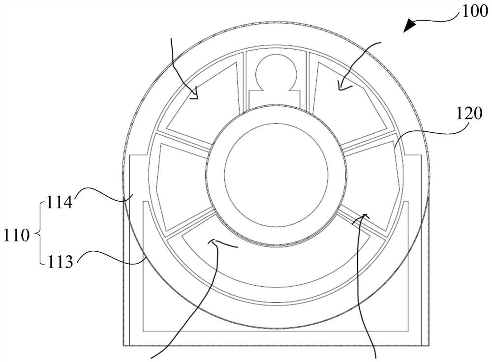
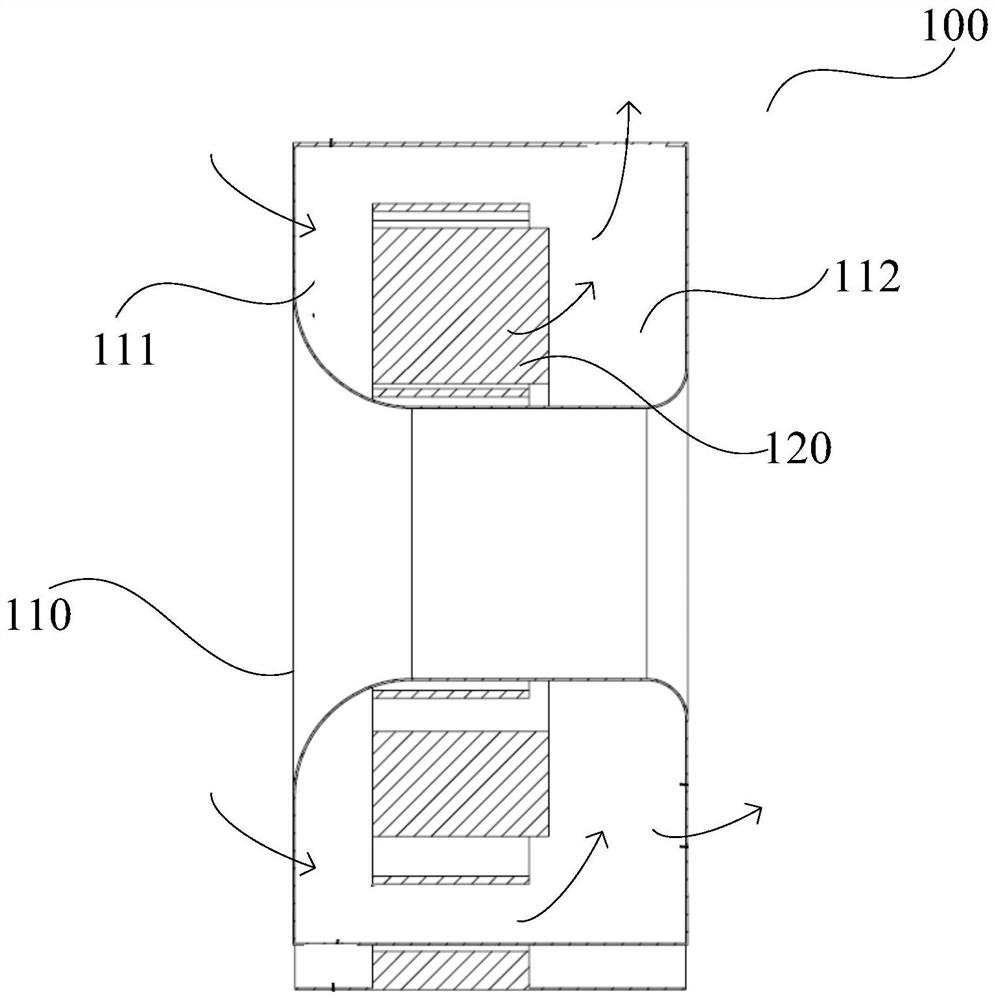
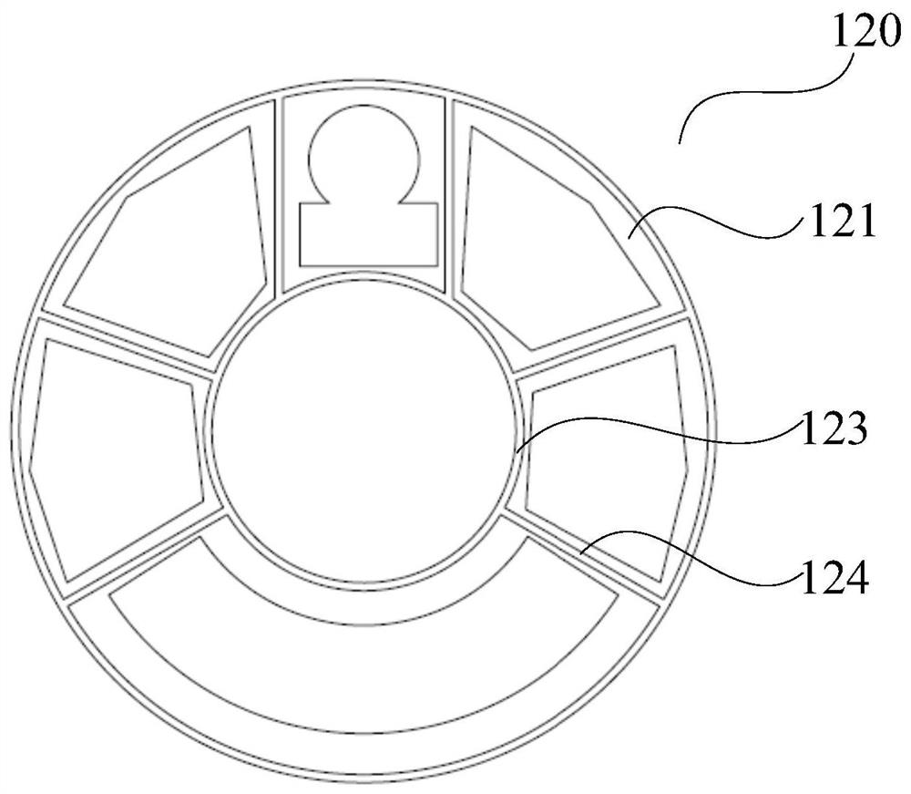
The invention provides a rack structure and CT equipment. The rack structure comprises a shell and a rack assembly. The rack assembly is arranged in the shell. The rack assembly comprises a fixed rackand a rotary rack. The fixed rack is provided with a first air cavity and a second air cavity which are formed by separating the shell in the axial direction. The rotating rack is rotatably mounted on the fixed rack and provided with a vent hole, and the vent hole communicates with the first air cavity and the second air cavity in the two sides of the rotating rack. The first air cavity, the venthole and the second air cavity are arranged in the axial direction, so that airflow enters the rotating rack in the axial direction and cools the electrical apparatus elements on the rotating rack, the airflow can effectively cool the electrical apparatus elements, it is guaranteed that the temperature field in the fixed rack is high in uniformity, the performance of the detector is prevented from being affected, and the imaging effect of images is guaranteed; and meanwhile, the overall height of the CT equipment can be reduced.

Description

technical field [0001] The invention relates to the technical field of imaging equipment, in particular to a frame structure and CT equipment. Background technique [0002] For current CT equipment, electrical components such as bulbs, high-voltage generators, and detectors are installed on a rotating support structure. Among them, high-power components such as bulbs and high-voltage generators will generate a lot of heat when they work, and the performance of the detector is more sensitive to temperature. As the support structure rotates within the device housing during operation, this makes the detector susceptible to heat sources such as bulbs. The high and unstable operating temperature in the equipment housing will affect the performance of the detector, which will cause image artifacts and affect the imaging quality. Contents of the invention [0003] Based on this, it is necessary to provide a frame structure and CT equipment that can ensure the performance of the...

Claims


Application Information

Patent Timeline
Patent Type & Authority Applications(China)
IPC IPC(8): A61B6/03
CPCA61B6/035A61B6/4435A61B6/4488
Inventor 缪俊杰杜岩峰
Owner SHANGHAI UNITED IMAGING HEALTHCARE
Why Eureka
Try Eureka