
Camera module and electronic equipment

A camera module and module technology, applied in the direction of TV, electrical components, color TV, etc., can solve the problem of camera occupancy, large space, etc., and achieve the effect of reducing interference, reducing manufacturing cost, and reducing occupied space

Inactive Publication Date: 2020-12-11
VIVO MOBILE COMM CO LTD
View PDF5 Cites 8 Cited by
  • Summary
  • Abstract
  • Description
  • Claims
  • Application Information

AI Technical Summary

Problems solved by technology

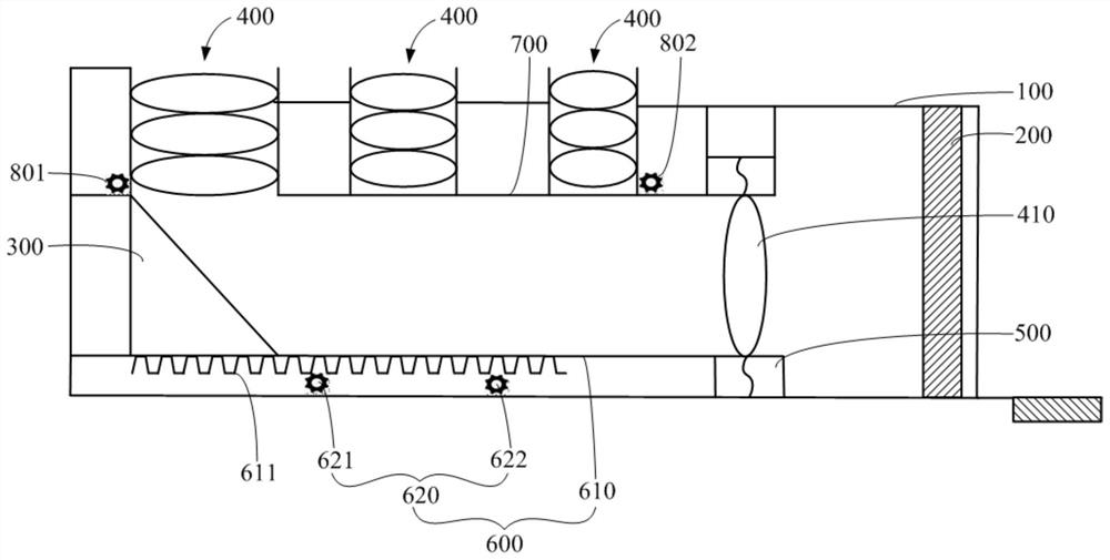
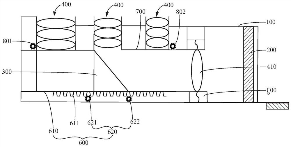
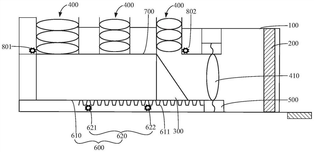
[0003] The invention discloses a camera module, which can solve the problem that cameras with many electronic devices occupy a large space

Method used


Image

  • Camera module and electronic equipment
  • Camera module and electronic equipment
  • Camera module and electronic equipment

Examples


Embodiment Construction

[0028] In order to make the purpose, technical solution and advantages of the present invention clearer, the technical solution of the present invention will be clearly and completely described below in conjunction with specific embodiments of the present invention and corresponding drawings. Apparently, the described embodiments are only some of the embodiments of the present invention, but not all of them. Based on the embodiments of the present invention, all other embodiments obtained by persons of ordinary skill in the art without making creative efforts belong to the protection scope of the present invention.

[0029] The technical solutions disclosed by various embodiments of the present invention will be described in detail below in conjunction with the accompanying drawings.

[0030] Please refer to Figure 1 to Figure 6 , the embodiment of the present invention discloses an electronic device, and the disclosed electronic device includes a module casing 100 , a photo...


PUM


Abstract

The invention discloses a camera module, which comprises a module shell (100), a photosensitive chip (200), a reflector (300) and a plurality of lens groups (400), the plurality of lens groups (400) are arranged on the module shell (100) at intervals, the photosensitive chip (200) is arranged in the module shell (100), the reflector (300) has a plurality of working positions, and the plurality ofworking positions are opposite to the plurality of lens groups (400) one by one. The reflector (300) is movably arranged in the module shell (100), the reflector (300) can be switched among a plurality of working positions, and under the condition that the reflector (300) is located at the working position, the reflector (300) can reflect ambient light penetrating through the corresponding lens groups (400) to the photosensitive chip (200). According to the scheme, the problem that more space is occupied when the electronic equipment is provided with a plurality of cameras in the prior art canbe solved. The invention further discloses electronic equipment.

Description

technical field [0001] The invention relates to the technical field of communication equipment, in particular to a camera module and electronic equipment. Background technique [0002] With the advancement of technology and the improvement of user needs, the performance of electronic equipment is continuously optimized. Among them, the more prominent performance is that the number of cameras equipped with current electronic equipment is increasing. A large number of cameras can meet the diverse shooting needs of users. However, a large number of cameras will occupy a large space, which is not conducive to assembly in electronic equipment. Contents of the invention [0003] The invention discloses a camera module, which can solve the problem that cameras with many electronic devices occupy a large space. [0004] In order to solve the problems of the technologies described above, the present invention is achieved in that: [0005] In the first aspect, the embodiment of t...

Claims


Application Information

Patent Timeline
Patent Type & Authority Applications(China)
IPC IPC(8): H04N5/225
CPCH04N23/57H04N23/55H04N23/54
Inventor 韩建国
Owner VIVO MOBILE COMM CO LTD
Learn More