
Precise positioning system

A positioning system and coordinate system technology, applied in the MCU field, can solve problems such as low positioning accuracy and short recognition distance

Pending Publication Date: 2020-12-11
UNITECH MECHATRONICS
View PDF4 Cites 0 Cited by
  • Summary
  • Abstract
  • Description
  • Claims
  • Application Information

AI Technical Summary

Problems solved by technology

The farther the distance between the camera and the marker, the lower the positioning accuracy
Also, these markers do not contain sub-markers of different sizes and styles to facilitate image recognition from different distances
In addition, passive or illuminated artificial markers have a shorter effective image recognition distance than projected markers

Method used


Image

  • Precise positioning system
  • Precise positioning system
  • Precise positioning system

Examples


Embodiment Construction

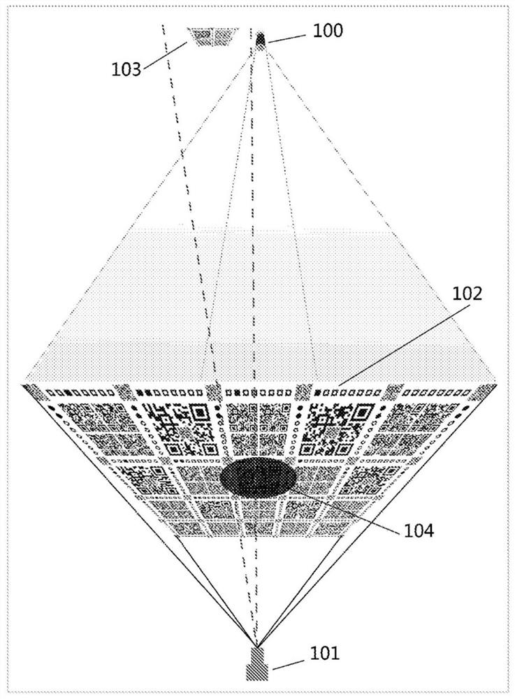
[0049] Such as figure 1 As shown, projector 100 projects a marker onto imaging panel 102 within the focal range of camera 101 . Imaging panel 102 is composed of optical filter material in its central region and diffuser material in the remainder of the region. Camera 101 may capture passive marker image 103 through optical filter 104 , or a marker image projected onto a diffused area of ​​imaging panel 102 .

[0050] Markers can appear in the form of QR codes or other image patterns that can be recognized and processed by the MCU.

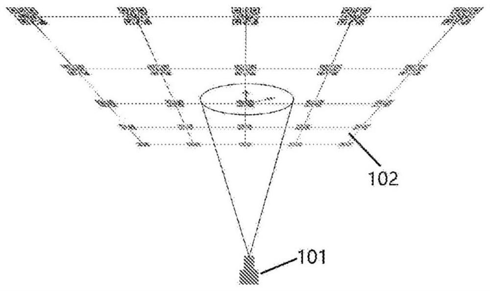
[0051] Such as figure 2 As shown, one or more images of the marker can be projected onto the panel 102, and the camera 101 captures the image and transmits it to the MCU for processing.

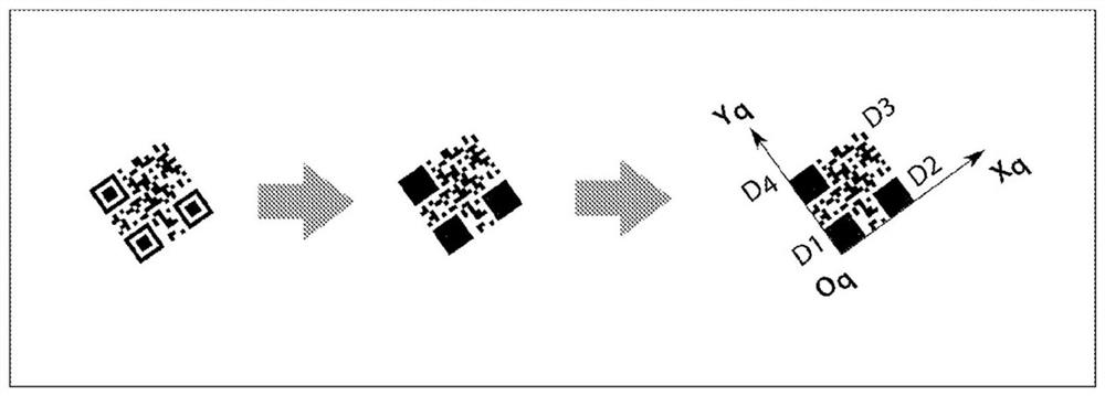
[0052] image 3 The MCU image processing process of a QR code (two-dimensional code) projected on the imaging panel is shown. The image captured on the panel is first converted to a black and white image, and then the three squares at the edge of the image a...


PUM


Abstract

A precise positioning system that can achieve less than a few millimetres position accuracy consists of a camera, an MCU, an imaging panel with its central area made of optical filtering material, andthe rest of the area made of diffusion material, an inertia measurement unit and an altimeter. The camera captures either a passive or projected landmark image and obtains its pose with respect to the landmark frame. If passive landmarks and landmark projectors are fixed at certain locations, their global poses are known. With known relationships between the positioning system and camera frames,landmark and world frames, the global pose of the positioning system with respect to world frame will be obtained. An altimeter can be used to get its altitude information. With the altitude information and global pose in XY plane, the system's global pose in 3-dimentional space can be determined.

Description

technical field [0001] The invention discloses an imaging panel, camera, inertial measurement unit, altimeter and MCU forming a precise positioning system for obtaining its attitude relative to passive or projected markers. Background technique [0002] Precise positioning systems are crucial for the navigation of mobile robots such as unmanned aerial vehicles (UAVs) or unmanned ground vehicles (UGVs). Positioning and positional accuracy are critical for some applications that require mobile operation. [0003] Positioning systems using ultrasonic sensors, infrared sensors, laser range finders, wireless beacons and vision are already on the market. [0004] The problem with positioning systems based on ultrasonic or infrared sensors is that the systems can only provide location information, not orientation. For easy navigation, mobile robots need additional sensors to obtain orientation information. [0005] The problem with positioning systems based on laser range finder...

Claims


Application Information

Patent Timeline
Patent Type & Authority Applications(China)
IPC IPC(8): G01C21/00G06K19/06
CPCG01C21/206G01C21/20
Inventor 夏庆华
Owner UNITECH MECHATRONICS
Learn More