Anti-seepage nut and opposite-pull screw assembly

A technology that pulls the screw and prevents water seepage. It is applied in the on-site preparation of building components, the connectors of formwork/formwork/work frame, and construction. It can solve problems such as loss, construction waste, and influence on decoration effects. Low cost, no construction waste, easy to manufacture

Pending Publication Date: 2020-12-15
何其佳
View PDF0 Cites 0 Cited by
  • Summary
  • Abstract
  • Description
  • Claims
  • Application Information

AI Technical Summary

Problems solved by technology

[0003] In the current aluminum formwork system, pull tabs are partially introduced instead of pull screws. Although the problem of water seepage in the wall is solved, the grout leakage caused by the gap between the pull tabs and the formwork is not easy to control when pouring concrete. Heavy-duty walls, The column still needs to be used together with the threaded screw, and construction waste will be generated due to the broken end of the pull piece. Moreover, since the break point of the pull piece is close to the wall surface, if the post-rust prevention treatment is not in place, it is easy for the rust to seep out of the wall surface and affect it. Decoration effect, resulting in greater losses

Method used


Image

  • Anti-seepage nut and opposite-pull screw assembly
  • Anti-seepage nut and opposite-pull screw assembly
  • Anti-seepage nut and opposite-pull screw assembly

Examples


Embodiment 1

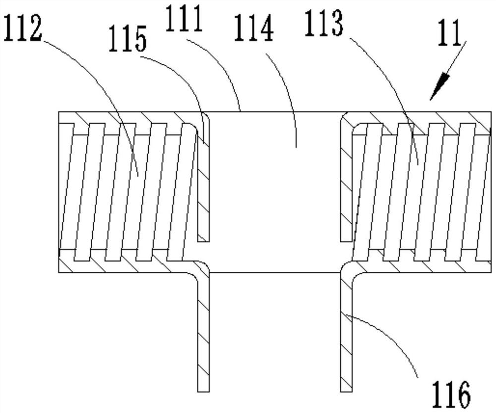
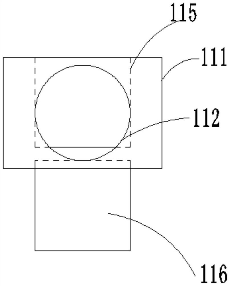
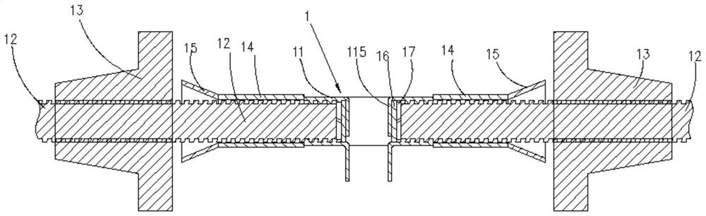
[0050] like figure 1 , 2 As shown, the anti-seepage nut 11 provided in this embodiment includes a body 111, a first connecting portion 112 with internal threads provided at one end of the body 111, and a first connecting portion 112 with internal threads provided at the other end of the body 111. The second connection part 113; the body 111 has at least one anti-seepage hole 114 arranged radially between the first connection part 112 and the second connection part 113; the first connection part 112 and the anti-seepage Internal barrier structures 115 are provided between the holes 114 and between the second connecting portion 113 and the anti-seepage hole 114 . When there are two or more anti-seepage holes 114, they are arranged side by side in sequence along the axial direction.

[0051] The above-mentioned radial direction refers to the cross-sectional direction of the anti-seepage nut, and the axial direction refers to the length direction of the anti-seepage nut.

[0052]...

Embodiment 2

[0060] like Figure 7 , 8 As shown, the first embodiment is repeated, the difference is that in this embodiment, the inner blocking structure 115 includes a first baffle 1151 and a second baffle 1152 oppositely arranged, and the first baffle 1151 and the second baffle The second baffle 1152 is a split structure, so that the inner barrier structure 115 partially isolates the anti-seepage hole 114 from the first connection portion 112 , and the anti-seepage hole 114 from the second connection portion 113 .

[0061] In this embodiment, the anti-seepage nut is located at the end side of the pull screw assembly, and the sleeve is only installed at one end of the anti-seepage nut, finally forming a Figure 9 Concrete wall panel construction shown.

Embodiment 3

[0063] like Figure 10 , 11 As shown, the first embodiment is repeated, the difference is that in this embodiment, the inner barrier structure 115 completely isolates the seepage-proof hole 114 from the first connecting portion 112, and separates the seepage-proof hole 114 from the first connection portion 112. The two connection parts 113 are completely isolated.

[0064] In this embodiment, the installation structure of the pull screw assembly and the concrete formwork installed with the anti-seepage nut is the same as that of Embodiment 1 or Embodiment 2.


PUM


Abstract

The invention provides an anti-seepage nut and an opposite-pull screw assembly. The anti-seepage nut comprises a body, a first connecting part and a second connecting part, wherein the first connecting part is arranged at one end of the body and provided with an internal thread, and the second connecting part is arranged at the other end of the body and provided with an internal thread; and at least one anti-seepage hole is formed in the position, between the first connecting part and the second connecting part, of the body in the radial direction. Compared with the prior art, on the premise that a building formwork is reinforced and the distance is positioned, the anti-seepage nut further ensures that poured concrete does not seep water, and the effects that the cost is low, manufacturingis easy, and no building rubbish exists are achieved.

Description

technical field [0001] The invention relates to the technical field of construction engineering, in particular to an anti-seepage nut and a pull screw assembly. Background technique [0002] In the construction of concrete buildings, in order to maintain the shape and thickness of the wall, it is necessary to use a tension screw device to control the distance between the formwork. However, due to cost issues, after the construction is completed, the parallel pull screw needs to be taken out and reused. This leaves a through hole in the concrete wall for the double pull screw. Water seepage in the wall cannot be avoided due to negligence in construction or differences in the bonding strength and thermal expansion and contraction coefficients of the two materials. Although the penetrating screw device in the technology of patent application number CN2015201146477 also has a good anti-seepage function, but it is necessary to leave the whole screw in the concrete, the material ...

Claims


Application Information

Patent Timeline
Patent Type & Authority Applications(China)
IPC IPC(8): E04G17/065
CPCE04G17/0655E04G17/0657
Inventor 何其佳
Owner 何其佳
Why Eureka
Try Eureka