Rigid body mark point optimization method and device and optical motion capture system

An optimization method and a technology of marking points, applied in the field of motion capture, can solve problems such as inaccurate rigid body matching, instability, and unstable rigid body posture, so as to improve motion capture accuracy, reduce the probability of problems, and inaccurate or inaccurate rigid body matching The effect of steady improvement

Pending Publication Date: 2020-12-15
SHENZHEN REALIS MULTIMEDIA TECH CO LTD
View PDF0 Cites 0 Cited by
  • Summary
  • Abstract
  • Description
  • Claims
  • Application Information

AI Technical Summary

Problems solved by technology

[0004] In order to solve the above technical problems, this application proposes a rigid body marker optimization method to improve rigid body attitude instability, inaccurate or unstable rigid body matching, etc., thereby reducing the probability of these problems in the motion capture system

Method used


Image

  • Rigid body mark point optimization method and device and optical motion capture system
  • Rigid body mark point optimization method and device and optical motion capture system
  • Rigid body mark point optimization method and device and optical motion capture system

Examples


Embodiment 1

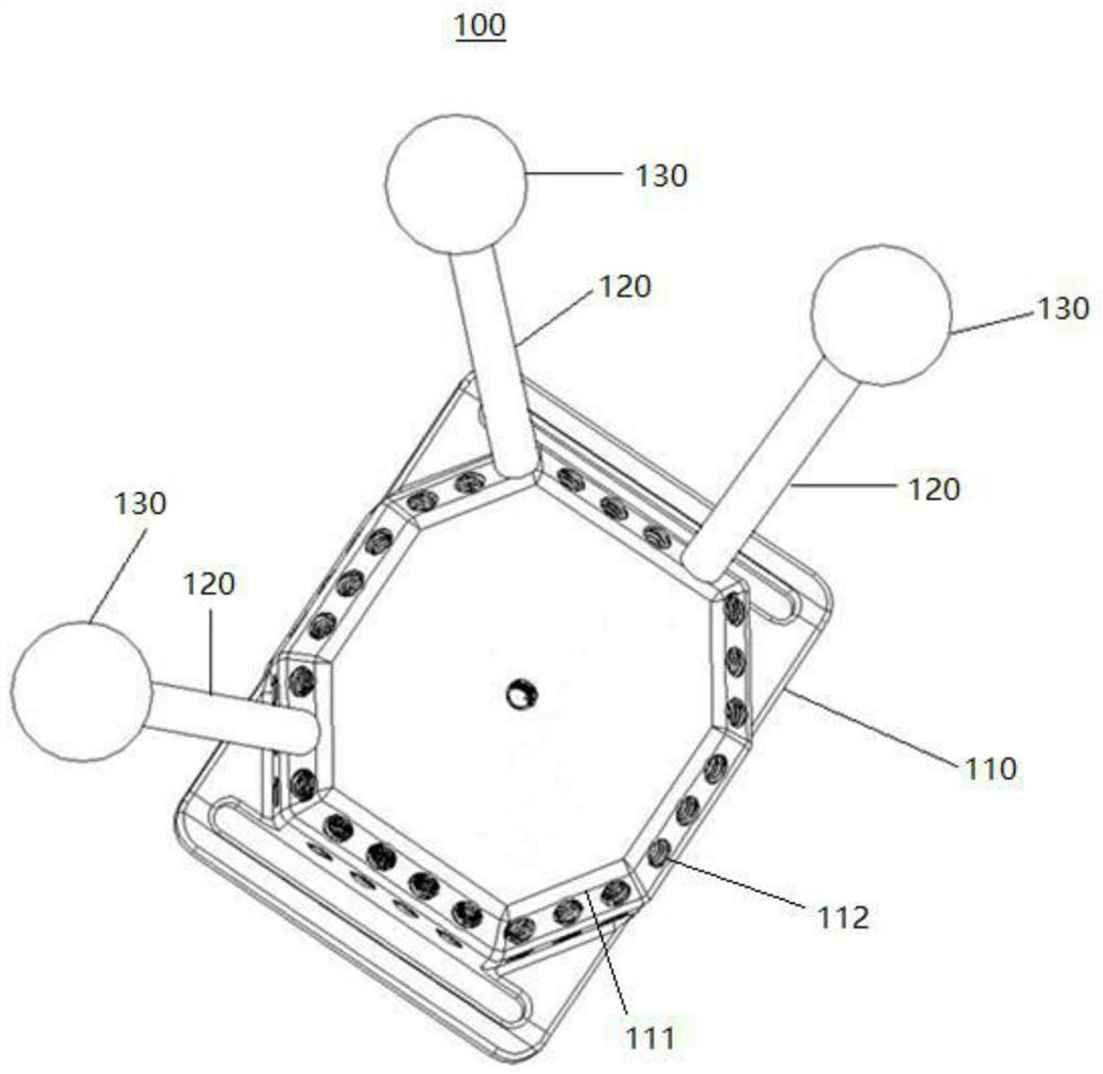
[0042] Please refer to figure 1 , the present application discloses a structural diagram of a rigid body. The rigid body structure 100 includes: a rigid body base 110, a threaded surface 111, a threaded slot 112, a support rod 120, a marking point 130, etc., and a plurality of threaded surfaces 111 are provided on the rigid body base 110. and a plurality of threaded slots 112 , the plurality of threaded slots 112 are distributed on the plurality of threaded surfaces 111 , the support rod 120 is inserted into the threaded slots 112 , and the marking point 130 is located at the top of the support rod 120 .

[0043] The rigid base 110 may be in any shape, that is, the rigid base 110 may be a cube, a cuboid, a cylinder or other shapes, which are not specifically limited here. The size of the threaded surface 111 can be set according to the actual situation. Generally, 1-16 threaded surfaces 111 are set on the rigid body base 110 to distribute a certain number of threaded slots 112...

Embodiment 2

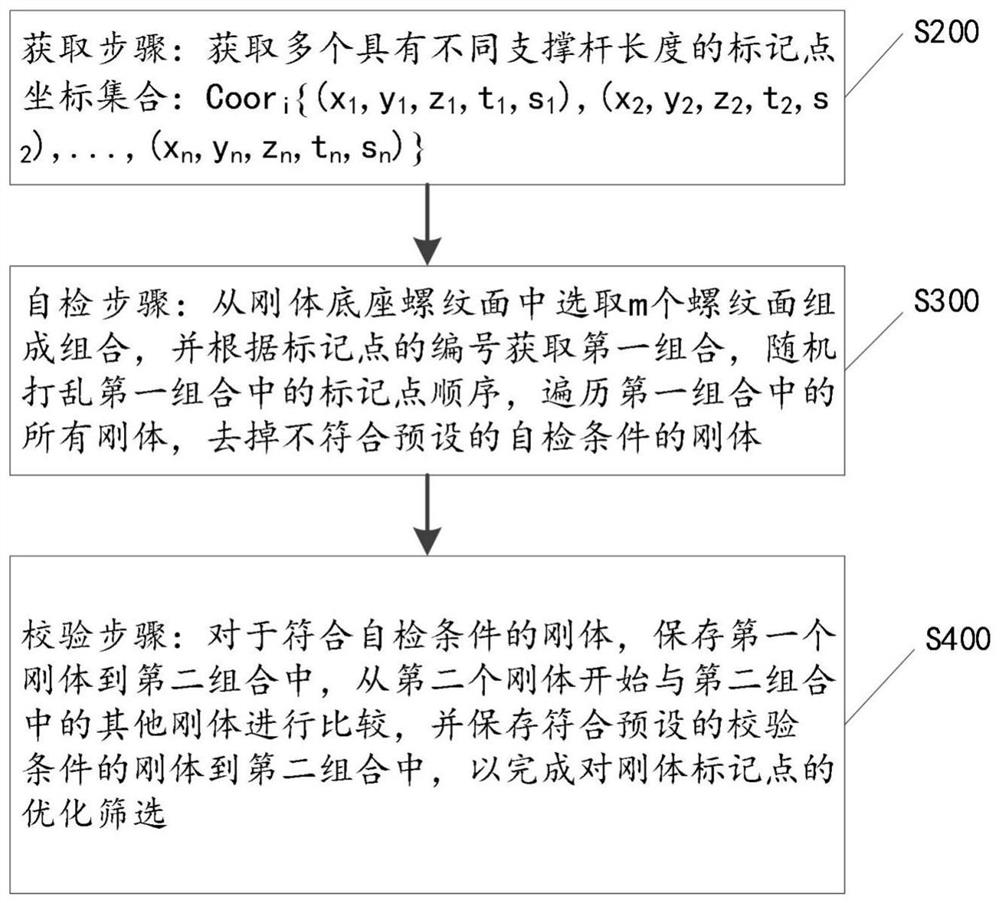
[0048] Please refer to figure 2 , after understanding figure 1 On the basis of the rigid body structure shown, this embodiment discloses a method of how to optimize the rigid body marking points. The method claimed includes steps S200-S500, which will be described separately below.

[0049] Step S200, obtaining step: obtaining a plurality of coordinate sets of marker points with different lengths of support rods: Coor i {(x 1 ,y 1 ,z 1 , t 1 ,s 1 ), (x 2 ,y 2 ,z 2 , t 2 ,s 2 ),..., (x n ,y n ,z n , t n ,s n )}, wherein, x, y, z represent three-dimensional coordinate values, i=1, 2, ..., a, represent the number of marking points, n=1, 2, ..., b, represent the number of threaded slots of the rigid body base , t ∈ {1, 2, ..., a} represents the number of the corresponding support rods with different lengths, and s ∈ {1, 2, ..., c} represents the number of the threaded surface of the rigid body base.

[0050] In an embodiment, this step S200 may include: obtaining...


PUM


Abstract

The invention discloses a rigid body mark point optimization method which comprises the following steps: an acquisition step: acquiring a plurality of mark point coordinate sets with different supportrod lengths, fusing parameters such as a threaded slot, a support rod and a threaded surface into the coordinate sets, and then removing rigid bodies which do not meet preset self-inspection conditions through a self-inspection step to obtain a plurality of mark point coordinate sets; storing the rigid bodies meeting the preset verification conditions into the second combination one by one through the verification step, wherein the rigid bodies stored in the second combination are the optimized rigid bodies. Through the optimization method, the problems of rigid body posture instability, rigid body matching inaccuracy or instability and the like existing in the dynamic capture system with the mark points are obviously improved, and meanwhile, the probability of the problems occurring in the dynamic capture system is obviously reduced.

Description

technical field [0001] The invention relates to the technical field of motion capture, in particular to a rigid body marking point optimization method, equipment and optical motion capture system. Background technique [0002] In the existing marker point motion capture system, there are certain requirements for the installation of the rigid body and the marker point, and the characteristics of the rigid body determine the accuracy of the system motion capture to a certain extent. In the existing marker point motion capture system, there are often problems such as unstable rigid body attitude, inaccurate or unstable rigid body matching, and these problems are almost inevitable. [0003] In order to reduce the probability of the above problems in the system, the following problems need to be solved: (1) For a single rigid body, all its marked points cannot be coplanar, because the attitude of the rigid body cannot be determined in this coplanar situation, and the rigid body ...

Claims


Application Information

Patent Timeline
Patent Type & Authority Applications(China)
IPC IPC(8): G06T17/10
CPCG06T17/10
Inventor 黄少光许秋子
Owner SHENZHEN REALIS MULTIMEDIA TECH CO LTD
Why Eureka
Try Eureka