Leg exercise chair for fitness
A technology for exercising chairs and legs is applied in the field of leg exercising chairs for fitness, which can solve the problems of single function, inconvenient exercise, and expensive fitness equipment, and achieve the effect of improving fitness and strengthening muscles.
- Summary
- Abstract
- Description
- Claims
- Application Information
AI Technical Summary
Problems solved by technology
Method used
Image
Examples
Embodiment 1
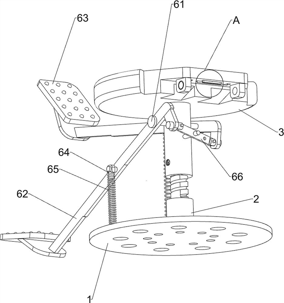
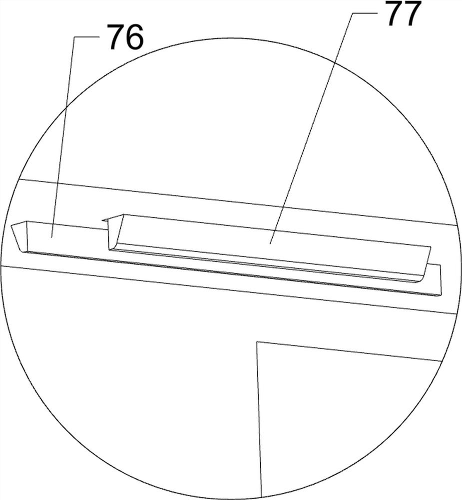
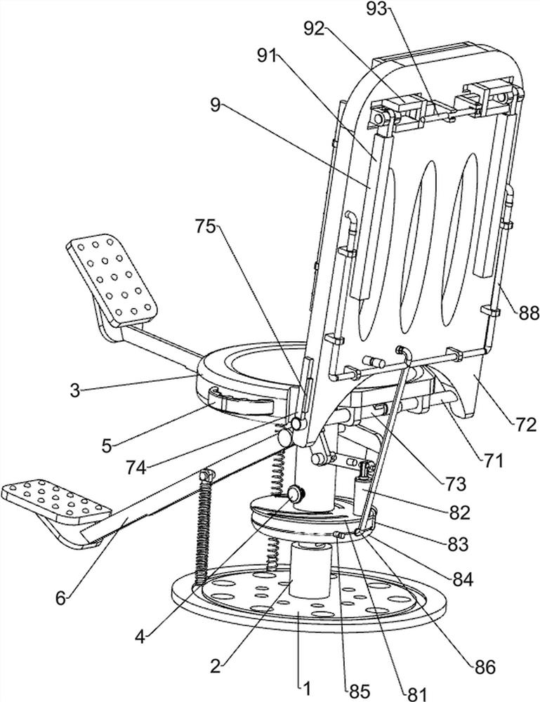
[0023] A kind of leg exercise chair for fitness, such as Figure 1-4 As shown, it includes a base 1, a support column 2, a disc 3, a positioning rod 4, an armrest 5, a swing mechanism 6, and an adjustment mechanism 7. The middle position of the top of the base 1 is connected with a support column 2, and the upper part of the support column 2 is threaded. The disc 3 is connected with the disc 3, the outer side of the lower part of the support column 2 is connected with the positioning rod 4, the left and right sides of the top of the support column 2 are connected with the handrail 5, and the swing mechanism 6 is connected between the base 1 and the disc 3. , the rear side of the disc 3 is connected with an adjustment mechanism 7 .
[0024] Swing mechanism 6 comprises fixed rod 61, connecting plate 62, pedal 63, bearing 64, pull-up spring 65 and connecting block 66, and the middle part of disc 3 is connected with fixed rod 61, and the left and right ends of fixed rod 61 are all...
Embodiment 2
[0029] On the basis of Example 1, such as figure 1 and figure 2 As shown, a cooling mechanism 8 is also included, and the cooling mechanism 8 includes a mounting plate 81, an air pump 82, a first air pipe 83, an air reservoir 84, an exhaust valve 85, a second air pipe 86, an air cushion 87, a third air pipe 88 and Outlet pipe 89, the bottom of disc 3 is connected with mounting plate 81, and the rear side of mounting plate 81 top is connected with pump 82, and the top of pump 82 is hingedly connected with the left side of connecting block 66, and the bottom of mounting plate 81 is connected There is an air storage tank 84, the first air pipe 83 is connected between the left side of the air storage tank 84 rear end and the bottom of the pump 82, the right side of the air storage tank 84 rear end is connected with an exhaust valve 85, and the bottom of the front side of the leaning plate 72 is connected with a Air cushion 87, the right side of air cushion 87 rear end is connect...
Embodiment 3
[0032] On the basis of Example 2, such as figure 2 As shown, support mechanism 9 is also included, and support mechanism 9 includes support block 91, U-shaped slide block 92 and strut 93, and the left and right ends of the rear side of the upper part of leaning plate 72 are hingedly connected with supporting block 91, leaning plate 72 Two U-shaped sliders 92 are slidably connected in the middle of the upper rear side, and the right end of the left U-shaped slider 92 is hingedly connected with a strut 93, and the strut 93 is connected to the left end of the right U-shaped slider 92 by clamping. connected in a connected manner.
[0033] When the user is going to fold down the backing plate 72, he can turn the support blocks 91 on the left and right sides to be in a vertical state with the backing plate 72, and then push the U-shaped sliders 92 on the left and right sides to slide outwards. When the sliding block 92 slides to the outermost end, the support bar 93 is moved to ma...
PUM
 Abstract
Description
Claims
Application Information
 - R&D
- Intellectual Property
- Life Sciences
- Materials
- Tech Scout
- Unparalleled Data Quality
- Higher Quality Content
- 60% Fewer Hallucinations
Browse by: Latest US Patents, China's latest patents, Technical Efficacy Thesaurus, Application Domain, Technology Topic, Popular Technical Reports.
© 2025 PatSnap. All rights reserved.Legal|Privacy policy|Modern Slavery Act Transparency Statement|Sitemap|About US| Contact US: help@patsnap.com


