
Small semi-automatic grinding machine special for kitchen knife

A special grinding machine and semi-automatic technology, which is applied in the direction of grinding machine parts, grinding workpiece supports, grinding/polishing equipment, etc., can solve the problems of unsatisfactory clamping effect, difficulty in manual sharpening, and inconvenient use. To achieve the effect of quick and flexible card installation and tool change, and stable and reliable tool card

Inactive Publication Date: 2020-12-18
冯震
View PDF6 Cites 0 Cited by
  • Summary
  • Abstract
  • Description
  • Claims
  • Application Information

AI Technical Summary

Problems solved by technology

[0002] Grinding kitchen knives is a craft. It seems very simple. Many people are engaged in this profession, but without professional equipment, they cannot reach the level of sharpening knives produced by knife manufacturers. Manual knives often encounter jumping edges, gaps, and wavy curves on the blade. It is not flat and needs to be trimmed and re-sharpened. When sharpening the blade, it is difficult to sharpen the knife by hand. A good knife, such as a new knife, is sharpened by the grinder used by the knife factory and then sharpened by the grinder with special equipment. Some grinders cannot grind different types of knives, and the clamping effect is not ideal, which brings inconvenience to people's use. For this reason, we propose a special grinder for small semi-automatic kitchen knives

Method used


Image

  • Small semi-automatic grinding machine special for kitchen knife
  • Small semi-automatic grinding machine special for kitchen knife
  • Small semi-automatic grinding machine special for kitchen knife

Examples


Embodiment Construction

[0019] The following will clearly and completely describe the technical solutions in the embodiments of the present invention with reference to the accompanying drawings in the embodiments of the present invention. Obviously, the described embodiments are only some, not all, embodiments of the present invention. Based on the embodiments of the present invention, all other embodiments obtained by persons of ordinary skill in the art without making creative efforts belong to the protection scope of the present invention.

[0020] In the description of this application, it should be noted that, unless otherwise clearly specified and limited, the terms "installed", "set with", "connected", etc. should be understood in a broad sense, such as "connected", which can be a fixed connection , can also be detachably connected, or integrally connected; can be mechanically connected, can also be electrically connected; can be directly connected, can also be indirectly connected through an i...


PUM


Abstract

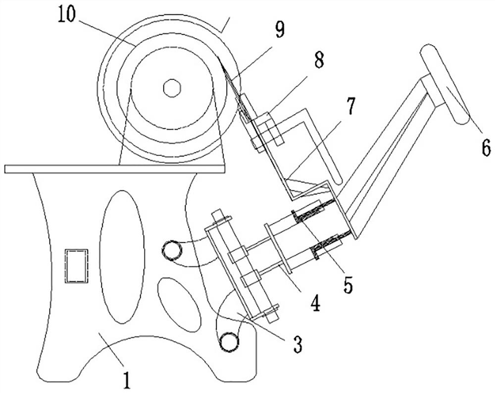
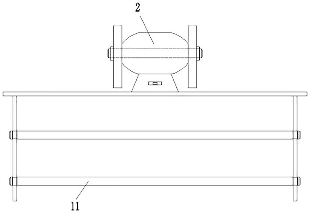
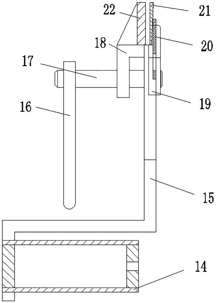
The invention discloses a small semi-automatic grinding machine special for a kitchen knife. The small semi-automatic grinding machine special for the kitchen knife comprises a machine body, a rotarysupporting sleeve and a rotary disc, wherein the inner surface of the machine body is fixedly connected with sliding rails, the front sides and the rear sides of the outer surfaces of the sliding rails are provided with knife table base body layers I, and meanwhile, the right sides of the knife table base body layers I are provided with knife table base body layers II. The machine body, the knifetable base body layers I, the knife table base body layers II, knife table base body layers III, a steering wheel, the rotary disc, a knife clamping device, the kitchen knife, the sliding rails and handles are arranged, through different knife feeding parts, edge forming and grinding can be realized, meanwhile, an inwards-concave edge shape is formed through grinding of a grinding wheel, then a chip groove is formed, thus the kitchen knife is light, smooth, free of knife clamping and labor-saving in use, in addition, a steering wheel handle core, the rotary supporting sleeve, the rotary disc,a locking master slice handle, a locking shaft, a supporting plate, a locking master slice, a knife clamping plate supporting plate, a knife clamping plate and a knife ejecting plate are arranged andcan be combined into a clamping device, so that the knife clamping is stable and reliable, and the clamping and knife replacing are fast and flexible.

Description

technical field [0001] The invention relates to the technical field of grinders, in particular to a special grinder for small semi-automatic kitchen knives. Background technique [0002] Grinding kitchen knives is a craft. It seems very simple. Many people are engaged in this profession, but without professional equipment, they cannot reach the level of sharpening knives produced by knife manufacturers. Manual knives often encounter jumping edges, gaps, and wavy curves on the blade. It is not flat and needs to be trimmed and re-sharpened. When sharpening the blade, it is difficult to sharpen the knife by hand. A good knife, such as a new knife, is sharpened by the grinder used by the knife factory and then sharpened by the grinder with special equipment. Some grinders cannot grind different types of knives, and the clamping effect is not ideal, which brings inconvenience to people's use. For this reason, we propose a special grinder for small semi-automatic kitchen knives. ...

Claims


Application Information

Patent Timeline
Patent Type & Authority Applications(China)
IPC IPC(8): B24B3/54B24B41/00B24B41/06
CPCB24B3/54B24B41/00B24B41/06
Inventor 冯震
Owner 冯震
Learn More