Wedged pin

A wedge and pin technology, applied in the direction of pins, connecting components, mechanical equipment, etc., can solve the problem of time-consuming, and achieve the effect of increasing the adjustability and simplifying the installation process.

Inactive Publication Date: 2003-09-10
HILTI AG
View PDF5 Cites 0 Cited by
  • Summary
  • Abstract
  • Description
  • Claims
  • Application Information

AI Technical Summary

Problems solved by technology

But this one-piece wedging pin can only be fixed in the mounting hole pre-cut in a special process
This process is very time consuming and additionally requires specially manufactured undercuts in order to be able to produce undercuts of the required depth

Method used


Image

  • Wedged pin
  • Wedged pin
  • Wedged pin

Examples


Embodiment Construction

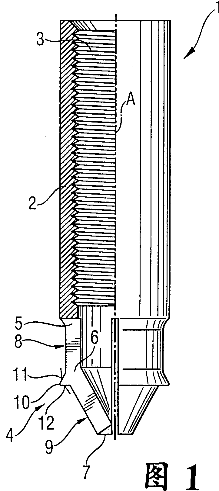
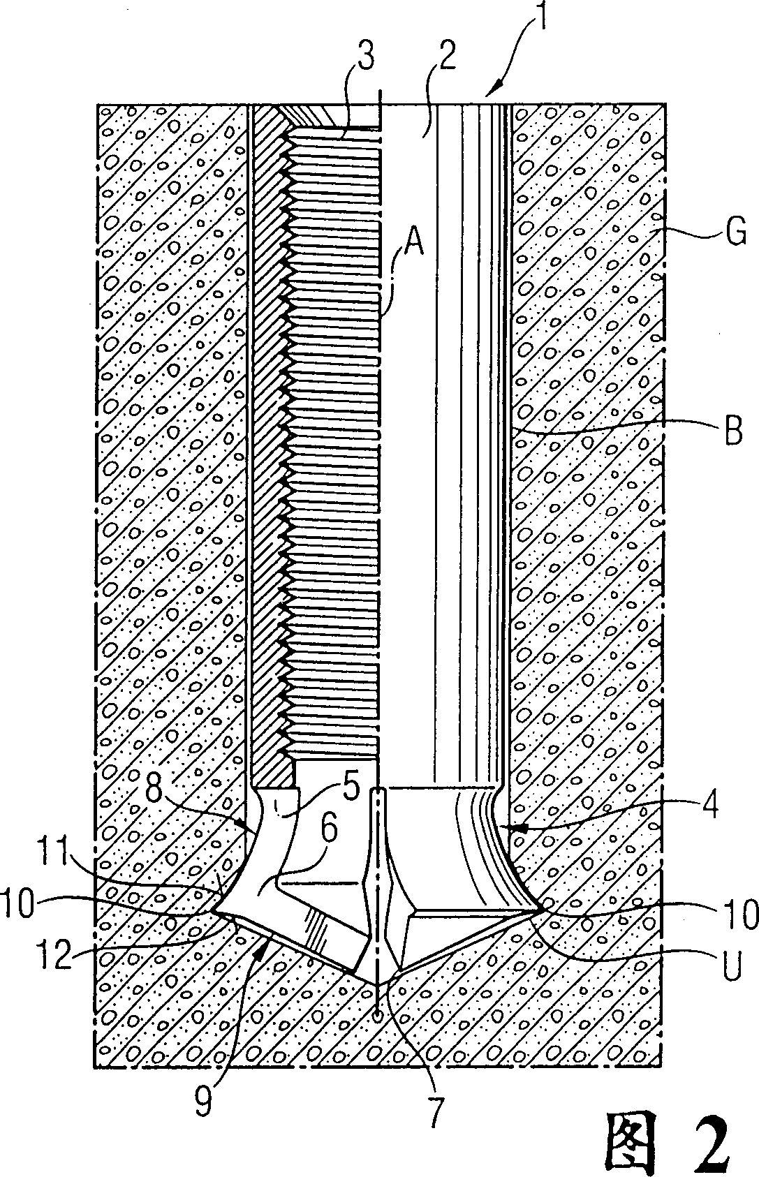
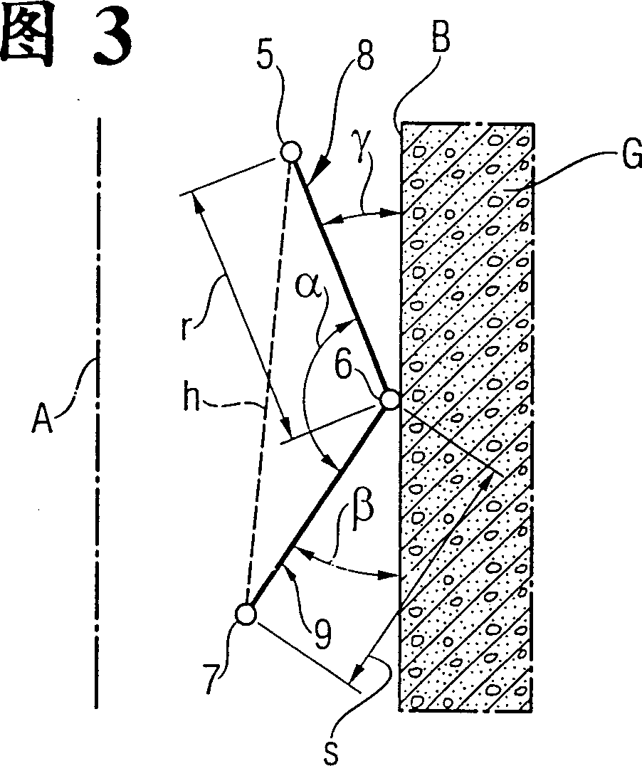
[0023] A first exemplary embodiment of a wedging pin according to the invention is generally designated by the symbol 1 in FIGS. 1 and 2 . It consists of a metal sleeve 2 provided with an internal thread 3, which has expansion arms on its front section 4, which are separated from each other by axial grooves. The expansion arm is connected to the sleeve 2 via an articulating transition zone, preferably a plastic joint 5, and has a flexible joint 6, by which the expansion arm is divided into a rear expansion arm 8 and a front expansion arm 9 . The front expansion arm 9 is distributed obliquely relative to the rear expansion arm 8 . The front end 7 of the front expansion arm 9 simultaneously constitutes the front end of the sheath 2 and is closer to the axis A of the sheath 2 than the plastic joint 5 .

[0024]As shown in FIG. 3 , the two spreading arms 8 , 9 form an angle of approximately 100° to 160°. The angle between the outer surface of the front expansion arm 9 and the p...


PUM


Abstract

A wedged pin is provided with a sleeve 2, having a load application means, in particular an inside screw 3, and at a front section 4 of the sleeve 2, are there transversing flexible and expandable arms separated by a longitudinal slot from each other. Chisel-like cutters (10) are provided on outer surfaces of joint-shaped transition regions formed from a rear expandable arm 8 to a front expandable arm 9, while the cutters substantially do not exceed the maximum outside diameter of the sleeve 2. The rear expandable arm 8 and the front expandable arm 9 form with each other an angle from about 100 DEG. to about 160 DEG., with a front end of the front expandable arm being located closer to a sleeve 2 longitudinal axis (A) than the joint-shaped transitional region.

Description

technical field [0001] The invention relates to a wedging pin with a sleeve with a support device, which sleeve has, on its front section, transversely flexible expansion arms separated by longitudinal grooves. Background technique [0002] The fixation of known wedging pins is mostly based on the expansion principle. The wedging expansion pins used for this usually consist of two parts and consist of a sleeve-shaped pin body with a tapered hole and an expansion element. For fixing in the pre-prepared mounting hole, the expansion element is hammered into the expansion area of ​​the sleeve-shaped pin body. As a result, the expansion region is spread radially and pressed against the wall of the mounting hole in a force-transmitting manner. The multi-piece nature of wedging expansion pins is known to cause problems. For example, the expansion element may be installed incorrectly in the bore of the pin body. It is also possible that the expansion element falls out of the hol...

Claims


Application Information

Patent Timeline
Patent Type & Authority Patents(China)
IPC IPC(8): F16B13/10F16B13/08F16B13/13
CPCF16B13/0858F16B13/08F16B13/00
Inventor 埃里希·维瑟马库斯·哈特曼卡伊-乌韦·凯勒米歇尔·维尔纳康金温
Owner HILTI AG
Why Eureka
Try Eureka