
Fixing device of pulley seat, rotary drilling rig and fixing method of power head

A technology for fixing devices and fixing methods, applied in rotary drilling rigs, drilling equipment and methods, directional drilling, etc., can solve the problems of reducing engineering construction efficiency, easy bending and pulling of pin shafts, consuming a lot of manpower and time, etc. To achieve the effect of convenient fixing and disassembly, good reliability and uniform force

Pending Publication Date: 2020-12-18
BEIJING SANY INTELLIGENT MFG TECH CO LTD
View PDF0 Cites 1 Cited by
  • Summary
  • Abstract
  • Description
  • Claims
  • Application Information

AI Technical Summary

Problems solved by technology

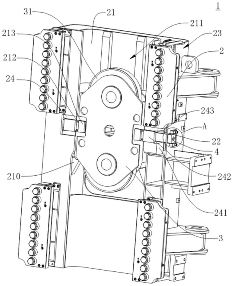
[0003] A typical rotary drilling rig includes a traveling mechanism, a mast, and a power head. The power head is the main working part of the rotary drilling rig. The power head is generally installed on the pulley seat through multiple screws, and then the pulley seat is installed on the It is used on a rotary drilling rig, but this installation method is inconvenient to disassemble the power head. If the power head is damaged and needs to be repaired or the power head needs to be maintained, the worker needs to disassemble the power head, which will consume a lot of manpower and time
[0004] In the prior art, when the power head is disassembled, one method is to remove all the bolts fixed between the power head and the pulley seat, so as to replace it, which is time-consuming and laborious, and reduces the efficiency of engineering construction; another method is to Remove the pin shaft between the pulley seat and the rotary drilling rig, and remove the power head and the pulley seat as a whole. However, during use, the pin shaft is prone to bending or indentation after being stressed, making it difficult to pull out the shaft and the shaft hole Difficult to assemble and disassemble

Method used


Image

  • Fixing device of pulley seat, rotary drilling rig and fixing method of power head
  • Fixing device of pulley seat, rotary drilling rig and fixing method of power head
  • Fixing device of pulley seat, rotary drilling rig and fixing method of power head

Examples


Embodiment Construction

[0032] The terms "first", "second", "third" and so on are only used for distinguishing descriptions, and do not represent sequence numbers, nor can they be understood as indicating or implying relative importance.

[0033] In addition, the terms "horizontal", "vertical", "overhanging" and the like do not mean that the components are absolutely horizontal or overhanging, but may be slightly inclined. For example, "horizontal" only means that its direction is more horizontal than "vertical", and it does not mean that the structure must be completely horizontal, but can be slightly inclined.

[0034] In the description of the present application, it should be noted that the orientation or positional relationship indicated by the terms "inner", "outer", "left", "right", "upper", "lower" etc. are based on the Orientation or positional relationship, or the orientation or positional relationship that the application product is usually placed in use, is only for the convenience of des...


PUM


Abstract

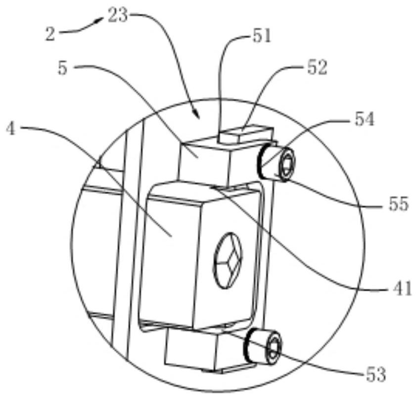
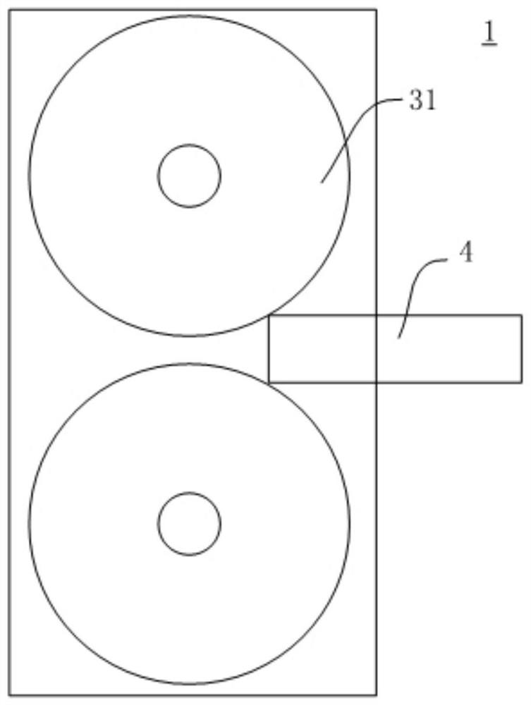
The invention discloses a fixing device of a pulley seat, a rotary drilling rig and a fixing method of a power head, and relates to the technical field of rotary drilling rigs. The fixing device of the pulley seat comprises a sliding frame body, the pulley seat and square pins; the sliding frame body is provided with a first guide groove and a plurality of first square holes, and the first squareholes are formed at the two sides of the sliding frame body respectively; pulleys are arranged on the pulley seat, the number of the pulleys is two, and the pulley seat is arranged in the first guidegroove; and the multiple square pins are arranged in the first square holes respectively and inserted between the two pulleys, and the pulley seat is detachably fixed to the sliding frame body throughcooperation of the square pins and the two pulleys. According to the device, the pulley seat is detachably fixed on the sliding frame body through matching of the square pins and the pulley seat, andthe power head is fixed on the pulley seat and the sliding frame body is fixed on a mast of the rotary drilling rig, so that the fixing device has the advantage that the power head can be conveniently fixed, disassembled and assembled.

Description

technical field [0001] The present application relates to the technical field of rotary drilling rigs, in particular to a fixing device for a pulley seat, a rotary drilling rig and a fixing method for a power head. Background technique [0002] With the rapid development of my country's economic construction, the market demand for construction machinery, especially various drilling rigs, is increasing. The construction process of modern construction projects generally starts with pile foundation construction. Therefore, pile hole construction is particularly important. With its advantages such as high production efficiency, rotary drilling rigs are increasingly widely used in pile hole operations under different geological conditions. [0003] A typical rotary drilling rig includes a traveling mechanism, a mast, and a power head. The power head is the main working part of the rotary drilling rig. The power head is generally installed on the pulley seat through multiple screw...

Claims


Application Information

Patent Timeline
Patent Type & Authority Applications(China)
IPC IPC(8): E21B7/02E21B7/04E21B3/02
CPCE21B3/02E21B7/02E21B7/04
Inventor 高志陈国广
Owner BEIJING SANY INTELLIGENT MFG TECH CO LTD
Learn More