A flange with loose warning function

A flange and function technology, applied in the field of flanges with a loose warning function, can solve the problems of low maintenance efficiency, looseness, and heavy inspection and maintenance workload, so as to avoid accidents, improve warning effects, and improve efficiency.

Active Publication Date: 2021-10-08
济南嘉德锻造有限公司
View PDF0 Cites 0 Cited by
  • Summary
  • Abstract
  • Description
  • Claims
  • Application Information

AI Technical Summary

Problems solved by technology

[0004] The purpose of the present invention is to solve the shortcomings in the prior art that when the traditional flange is used, the workload of the staff is large, the maintenance efficiency is low, and at the same time, it is impossible to take the initiative to give an early warning to the flange failure accident, and proposes a Flange with loose warning function

Method used


Image

  • A flange with loose warning function
  • A flange with loose warning function
  • A flange with loose warning function

Examples


Embodiment 1

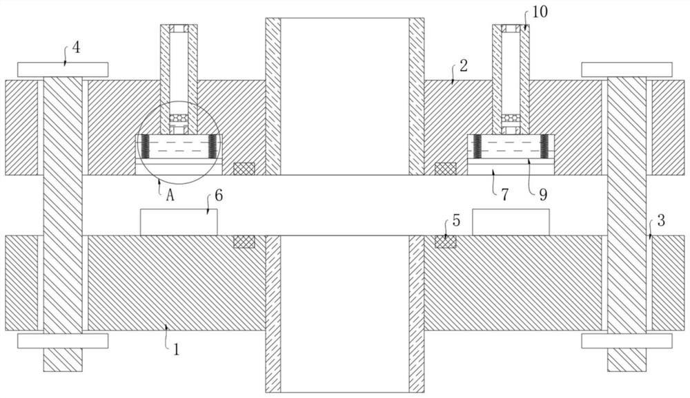
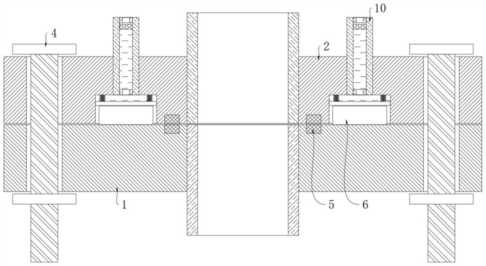
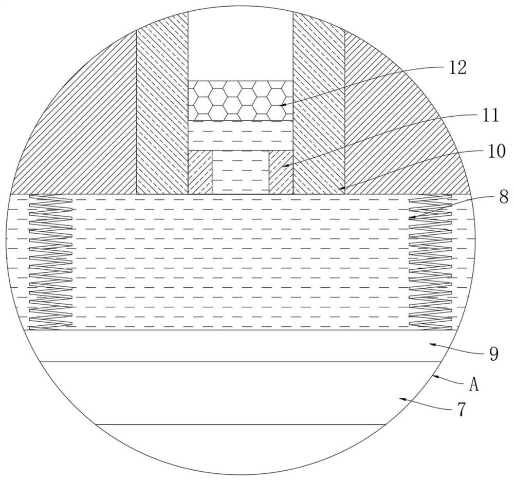
[0022] refer to Figure 1-3 , a flange with a loose warning function, including a first flange 1 and a second flange 2, the first flange 1 and the second flange 2 are correspondingly provided with a plurality of threaded holes 3, corresponding Locking bolts 4 are threaded in the two threaded holes 3, and the side of the first flange 1 close to the second flange 2 is evenly and fixedly connected with a plurality of blocks 6 corresponding to the locking bolts 4. A side of the second flange 2 close to the first flange 1 is evenly provided with a plurality of installation grooves 7 that cooperate with the block 6, and each installation groove 7 is elastically connected with a piston plate 9 by a return spring 8, and Each piston plate 9 is sealed and slidably connected with the groove wall of the corresponding installation groove 7 through a sealing ring. The sealed space formed by the piston plate 9 and the installation groove 7 is the driving area, and the driving area is filled ...

Embodiment 2

[0026] refer to Figure 4-5 The difference between this embodiment and Embodiment 1 lies in that: the inner wall of each display tube 10 is symmetrically embedded with conductive blocks 15, the indicating block 12 is made of conductive material, and the upper end surface of the second flange 2 is uniformly provided with multiple An alarm 14 corresponding to the display tube 10, a battery 13 is installed on the second flange 2, and the corresponding two conductive blocks 15 and the alarm 14 are electrically connected to the battery 13 through wires.

[0027] This embodiment can illustrate its functional principle through the following operation mode: when any locking bolt 4 is loosened so that the indicating block 12 in the corresponding display tube 10 moves downward, the indicating block 12 is offset against the two conductive blocks 15, and the circuit Conduction, the corresponding alarm 14 works, and the alarm 14 actively sends out a warning signal, so that the patrol perso...


PUM


Abstract

The invention discloses a flange with a loosening warning function, which comprises a first flange and a second flange. The first flange and the second flange are correspondingly provided with a plurality of threaded holes, corresponding to The two threaded holes are jointly threaded with locking bolts, and the side of the first flange close to the second flange is evenly and fixedly connected with a plurality of blocks corresponding to the locking bolts. A side surface of the second flange close to the first flange is uniformly provided with a plurality of mounting grooves for matching with the abutting blocks. In the present invention, by setting the indicator block, the display tube, the piston plate and the return spring, when the corresponding locking bolt becomes loose, the piston plate and the return spring cooperate to control the movement of the indicator block in the display tube, so that the maintenance personnel can check the flange. During the inspection, it is only necessary to directly check the position of the corresponding indicator block to know whether the corresponding locking bolt is loose, without using tools for detection, which improves the efficiency of inspection and maintenance.

Description

technical field [0001] The invention relates to the technical field of flanges, in particular to a flange with a loosening warning function. Background technique [0002] Flange is a pipeline connection tool. Flange connection mainly refers to a detachable connection consisting of flanges, gaskets and bolts connected to each other as a combined sealing structure. Due to the stable flange connection structure and good sealing performance, Therefore, the flange connection is widely used in gas-liquid transportation fields such as gas supply, water supply, and oil supply. [0003] However, when the traditional flange is applied to some high-pressure pipelines, the bolts and nuts will loosen after a period of use due to the high-pressure environment in the pipeline, resulting in leakage, and the slight looseness cannot be found intuitively, so the staff only It is possible to pass the inspection of tools one by one, which increases the labor load of maintenance personnel, and d...

Claims


Application Information

Patent Timeline
Patent Type & Authority Patents(China)
IPC IPC(8): F16L23/036F16L23/032G01D5/12
CPCF16L23/032F16L23/036G01D5/12
Inventor 张一宁
Owner 济南嘉德锻造有限公司
Why Eureka
Try Eureka