Coiled optical fiber supporting frame

A technology of support frame and optical fiber, applied in the field of support frame, can solve the problems of inability to adjust, inconvenient installation of support frame, and insufficient comprehensiveness, and achieve the effect of convenient installation and stable connection effect.

Inactive Publication Date: 2020-12-22
湖南彗驰科技有限公司
View PDF1 Cites 0 Cited by
  • Summary
  • Abstract
  • Description
  • Claims
  • Application Information

AI Technical Summary

Problems solved by technology

[0002] The disk-mounted fiber support frame is a frame used for the disk-mounted fiber support, but the fiber support frame of the existing patent CN207557550U still has certain disadvantages; first, the existing disk-mounted fiber support frame cannot It is not comprehensive enough to adjust a certain amount of coiled optical fibers. Secondly, it is inconvenient to install the support frame on the support column. For this reason, we propose a coiled optical fiber support frame

Method used


Image

  • Coiled optical fiber supporting frame
  • Coiled optical fiber supporting frame
  • Coiled optical fiber supporting frame

Examples


Embodiment 1

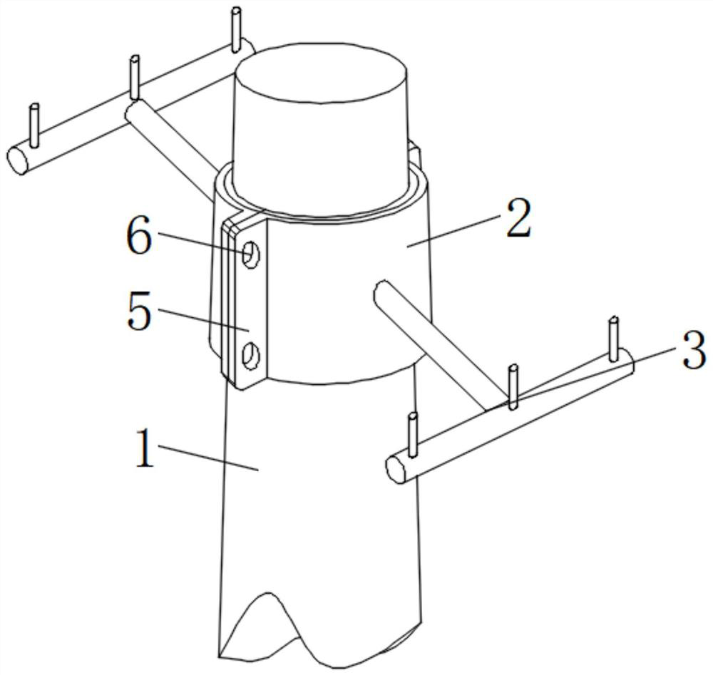
[0024]Such asfigure 1 As shown, a tray-mounted optical fiber support frame includes a support column 1, a support sleeve 2 is provided on the outer surface of the support column 1, and an adjustment structure 3 is provided on the outer surface of the support sleeve 2. The adjustment structure 3 includes a transverse connecting column 31 and a matching The connecting column 32, the threaded hole 33, the connecting thread 34 and the threaded connecting column 35 are provided with a rubber layer 4 on the inner side of the support sleeve 2, a connecting plate 5 is provided on one side of the support sleeve 2, and a connecting plate is provided on the outer surface of the connecting plate 5. Hole 6.

Embodiment 2

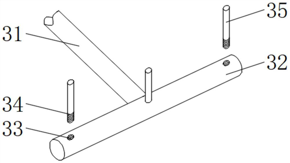
[0026]On the basis of Example 1, such asfigure 2 As shown, the horizontal connecting column 31 is provided on the outer surface of the support sleeve 2, the matching connecting column 32 is provided on the outer surface of the top end of the horizontal connecting column 31, the threaded hole 33 is provided on the outer surface of the upper end of the matching connecting column 32, and the threaded connecting column 35 is provided with Inside the threaded hole 33, the lower end of the threaded connecting column 35 is provided with a connecting thread 34, which is beneficial to the layout effect between the support frame components.

[0027]The number of adjustment structures 3 is two groups, the horizontal connecting column 31 and the support sleeve 2 are fixedly connected, the matching connecting column 32 and the horizontal connecting column 31 are fixedly connected, and the number of threaded holes 33 on the single adjusting structure 3 is three. The threaded hole 33 is matched with ...

Embodiment 3

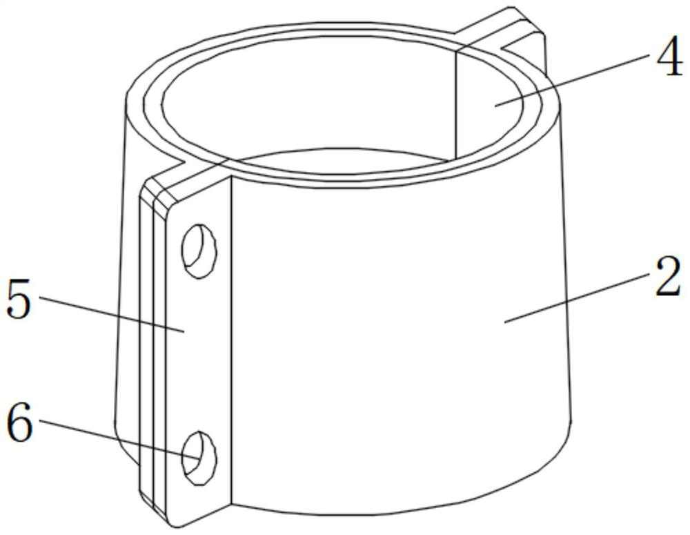
[0029]On the basis of Example 1 and Example 2, such asimage 3 ,4As shown, the number of support sleeves 2 is two groups, the support sleeves 2 are in the shape of a semicircular hollow column, the two groups of support sleeves 2 are in the shape of a hollow truncated cone when the inner side is attached, and the support sleeve 2 and the rubber layer 4 are movably connected. The rubber layer 4 is matched with the supporting sleeve 2, and the rubber layer 4 is matched with the supporting column 1, which is beneficial to the connection between the rubber layer 4 and the supporting sleeve 2.

[0030]The number of connecting plates 5 is four groups, the connecting plates 5 are arranged in a vertical strip shape, the connecting plates 5 and the supporting sleeve 2 are fixedly connected, and the connecting plates 5 are arranged symmetrically, which is beneficial to the connection between the connecting plate 5 and the supporting sleeve 2. Stable effect of the connection between.

[0031]The numb...


PUM


Abstract

The invention discloses a coiled optical fiber supporting frame which comprises a supporting column, a supporting sleeve is arranged on the outer surface of the supporting column, an adjusting structure is arranged on the outer surface of the supporting sleeve, the adjusting structure comprises a transverse connecting column, a matching connecting column, a threaded hole, a connecting thread and athreaded connecting column, and a rubber layer is arranged on the inner side of the supporting sleeve. A connecting plate is arranged on one side of the supporting sleeve, and a connecting through hole is formed in the outer surface of the connecting plate. According to the coiled optical fiber supporting frame, by arranging the adjusting structure, supporting frame components can be adjusted conveniently according to the number of coiled optical fibers, so that the practicability of equipment is high, and by arranging the supporting sleeve, the rubber layer, the connecting plate and the connecting through hole and matching with corresponding bolts and corresponding bolt caps, the supporting frame can be mounted on the supporting column, so that the supporting frame components can be mounted more conveniently.

Description

Technical field[0001]The invention relates to the field of support frames, in particular to a disk-mounted optical fiber support frame.Background technique[0002]The tray-mounted optical fiber support frame is a type of frame used for tray-mounted optical fiber support, but the fiber support frame of the existing published patent CN207557550U still has certain disadvantages; first, the existing tray-mounted optical fiber support frame cannot be based on actual conditions. A certain degree of adjustment is required for the number of disk-mounted optical fibers, which is not comprehensive enough. Secondly, the installation of the support frame on the support column is relatively inconvenient. For this reason, we propose a disk-mounted optical fiber support frame.Summary of the invention[0003]The main purpose of the present invention is to provide a disk-mounted optical fiber support frame, which can effectively solve the problems in the background art.[0004]In order to achieve the abov...

Claims


Application Information

Patent Timeline
Patent Type & Authority Applications(China)
IPC IPC(8): G02B6/46
CPCG02B6/46
Inventor 吴何生王小知李金玉王芳
Owner 湖南彗驰科技有限公司
Why Eureka
Try Eureka