A crane lifting mechanism

A hoisting mechanism, crane technology, applied in the direction of the spring mechanism, hoisting device, etc., can solve the problems of inconvenient hoisting and lifting, and achieve the effect of reducing the use limitation

Active Publication Date: 2020-06-16
河南省中原矿山设备有限公司
View PDF9 Cites 0 Cited by
  • Summary
  • Abstract
  • Description
  • Claims
  • Application Information

AI Technical Summary

Problems solved by technology

[0002] As we all know, the crane hoisting mechanism is a kind of auxiliary device used for cranes to lift and lower objects, and it has been widely used in the field of hoisting machinery; the existing crane hoisting mechanism includes a base plate, a left support plate, The right support plate, lifting motor, reducer and reel, the bottom ends of the left support plate and the right support plate are respectively connected with the left and right sides of the top of the bottom plate, the output end of the right part of the lifting motor is connected with the left part of the reducer The input end is connected, and the right output end of the reducer is provided with a transmission shaft, the right end of the transmission shaft passes through the inner upper side of the left support plate from the left end of the left support plate and extends to the outside of the right end of the left support plate, and the reel is set Between the left support plate and the right support plate, and the left end of the reel is connected with the left end of the transmission shaft, the right end of the reel is connected with the rotatable shaft on the left end of the right support plate, and the outer left and right sides of the reel are respectively The fixed suit is provided with a left baffle plate and a right baffle plate, and a steel wire rope is wound on the drum, and the steel wire rope is located between the left baffle plate and the right baffle plate, and one end of the wire rope is fixedly connected with the peripheral outer wall of the drum; When using the hoisting mechanism, first connect the other end of the wire rope to the external hoisting device, and then fix and bind the hoisting device to the hoisted object. Control the rotation of the lifting motor to drive the rotation of the reel to wind and release the wire rope to realize the lifting or lowering of the object; it is found in the use of the existing crane lifting mechanism that it is inconvenient during use. Timely braking control of the reel at the starting position, resulting in high limitations in use; and the wire rope is easily confused during the winding process on the reel, and the arrangement effect of the wire rope on the reel is poor, resulting in low reliability in use

Method used


Image

  • A crane lifting mechanism
  • A crane lifting mechanism
  • A crane lifting mechanism

Examples


Embodiment Construction

[0022] The specific implementation manners of the present invention will be further described in detail below in conjunction with the accompanying drawings and embodiments. The following examples are used to illustrate the present invention, but are not intended to limit the scope of the present invention.

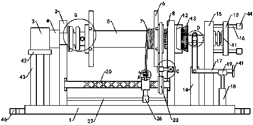
[0023] Such as Figure 1 to Figure 6As shown, a kind of crane hoisting mechanism of the present invention comprises base plate 1, left support plate 2, right support plate, lifting motor 3, speed reducer 4 and reel 5, the bottom end of left support plate 2 and right support plate They are respectively connected to the left side and the right side of the top of the base plate 1, the right output end of the lifting motor 3 is connected to the left input end of the reducer 4, and the right output end of the reducer 4 is provided with a transmission shaft. The right end passes through the inner upper side of the left support plate 2 from the left end of the left support plate...


PUM


Abstract

The invention relates to the technical field of lifting machinery accessory devices, in particular to a lifting mechanism of a crane. During usage, timely braking control over a roller is convenient according to the actual lifting position, and the limitation of use is reduced; and a wire rope is prevented from being disarranged on the roller in the welding process, the arrangement effect of the wire rope on the roller is improved, and the use reliability is improve. The lifting mechanism comprises a bottom plate, a left support plate, a right support plate, a lifting motor, a speed reducer and the roller; the lifting mechanism comprises a connecting shaft, a support shaft, a limiting plate, a connecting spring, a chuck, a cone brake disc, a fixing plate, a support column, an upper supportsliding column, a lower support column, an angle shift lever, an electric telescopic cylinder and a U-shape trough frame; and the lifting mechanism further comprises a reciprocating screw, universalrollers, a connecting column, a placement plate, a left supporting plate, a right supporting plate, a guiding shaft, a limiting sliding block, a limiting sliding column and a transmission belt; the lower side of the right end of the left supporting plate is provided with a left fixing groove; and a left ball bearing is arranged in the left fixing groove.

Description

technical field [0001] The invention relates to the technical field of hoisting machinery attachments, in particular to a hoisting mechanism of a crane. Background technique [0002] As we all know, the crane hoisting mechanism is a kind of auxiliary device used for cranes to lift and lower objects, and it has been widely used in the field of hoisting machinery; the existing crane hoisting mechanism includes a base plate, a left support plate, The right support plate, lifting motor, reducer and reel, the bottom ends of the left support plate and the right support plate are respectively connected with the left and right sides of the top of the bottom plate, the output end of the right part of the lifting motor is connected with the left part of the reducer The input end is connected, and the right output end of the reducer is provided with a transmission shaft, the right end of the transmission shaft passes through the inner upper side of the left support plate from the left ...

Claims


Application Information

Patent Timeline
Patent Type & Authority Patents(China)
IPC IPC(8): B66D1/12B66D1/14B66D1/28B66D1/38B66D5/14
CPCB66D1/12B66D1/14B66D1/28B66D1/38B66D5/14
Inventor 赵建军李好选
Owner 河南省中原矿山设备有限公司
Why Eureka
Try Eureka