Eureka AIR delivers breakthrough ideas for toughest innovation challenges, trusted by R&D personnel around the world.

Mold

A technology for molds and components, applied in the field of molds, can solve problems such as reducing the quality of slabs and reducing the life of molds, and achieve the effects of inhibiting wear, improving compensation rates, and preventing solidification delay phenomenon.

Active Publication Date: 2020-12-22
浦项股份有限公司
View PDF12 Cites 0 Cited by
  • Summary
  • Abstract
  • Description
  • Claims
  • Application Information

AI Technical Summary

Problems solved by technology

However, in this case, wear occurs between the short side of the slab and the short side portion of the mold to reduce the life of the mold and lower the quality of the slab

Method used


Image

  • Mold
  • Mold
  • Mold

Examples


Embodiment Construction

[0061] Hereinafter, embodiments will be described in detail with reference to the accompanying drawings. However, this disclosure may be embodied in many different forms and should not be construed as limited to the embodiments set forth herein; rather, these embodiments are provided so that this disclosure will be thorough and complete, and will The concept is fully conveyed to those skilled in the art.

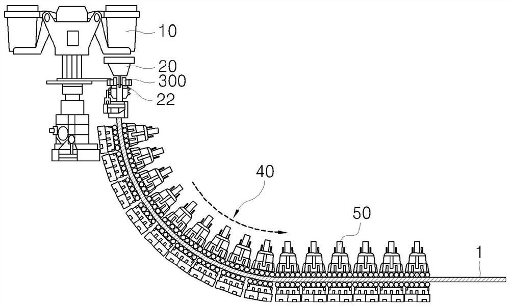
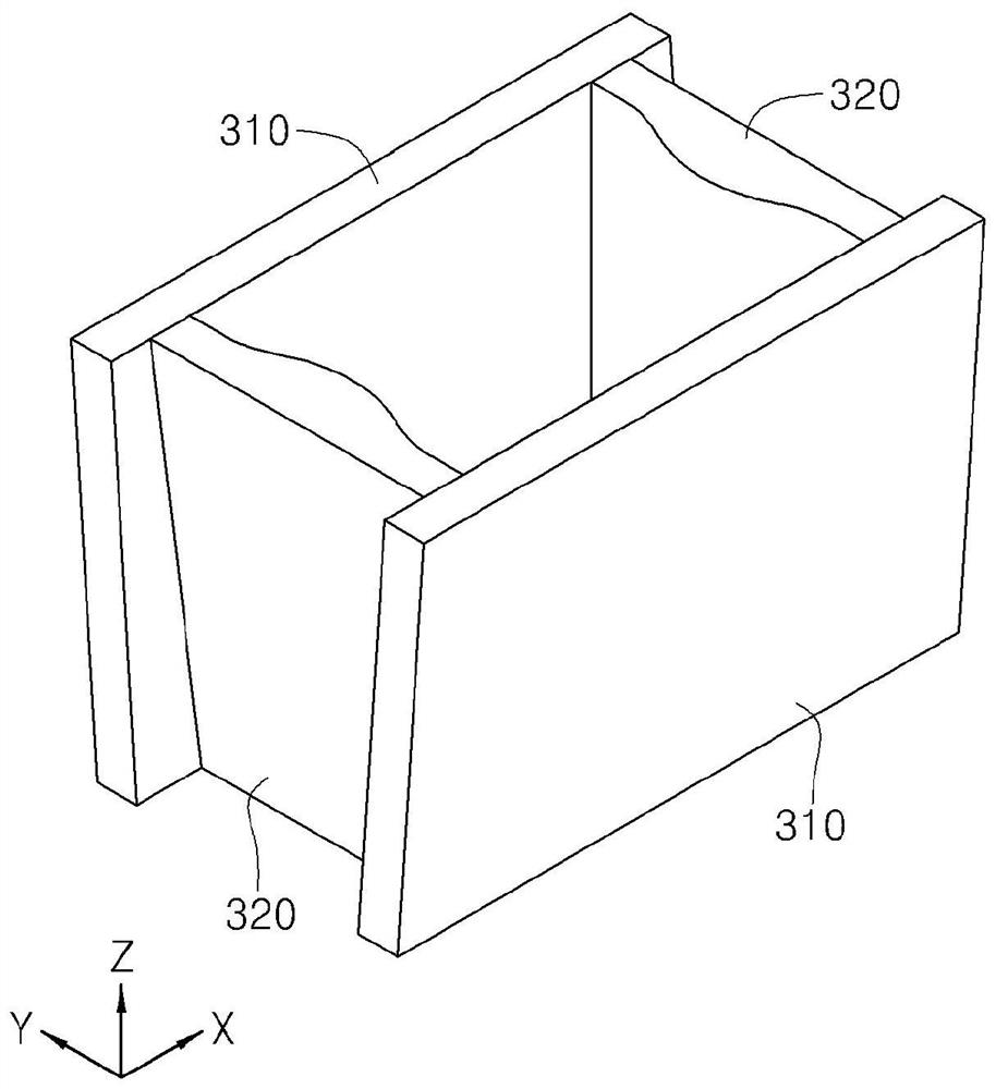
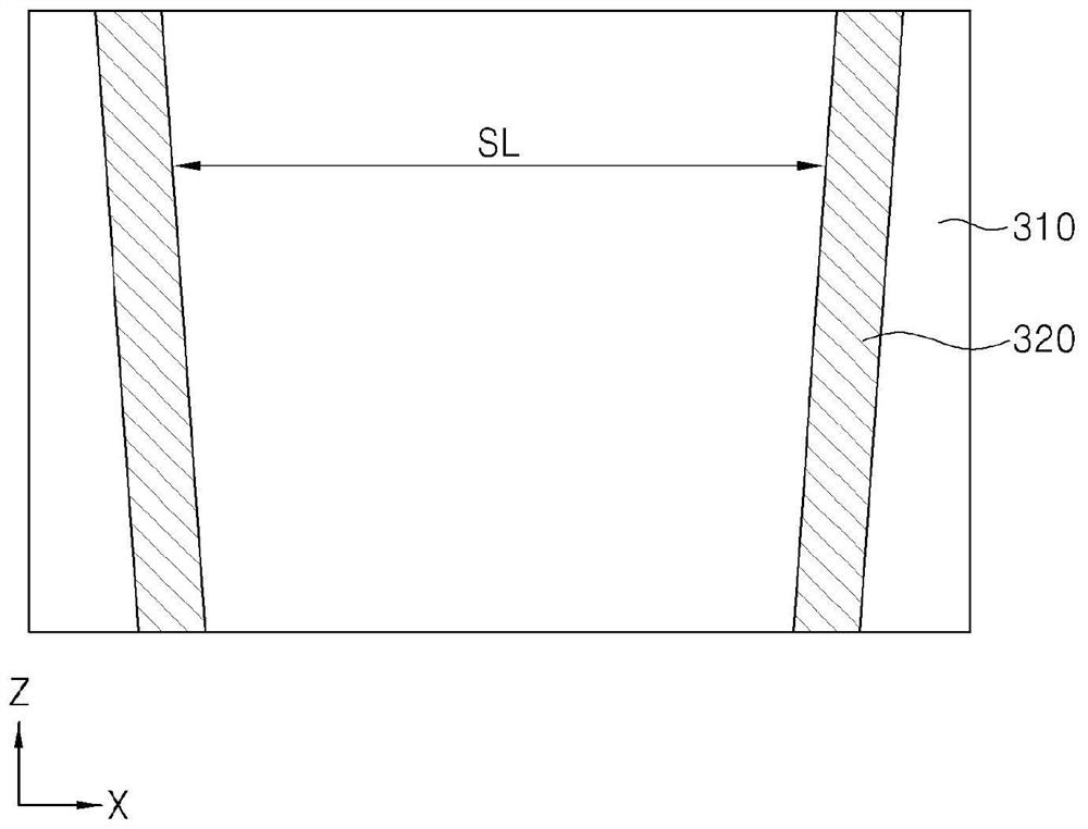
[0062] figure 1 is a view illustrating a main part of a general continuous casting facility. figure 2 is a three-dimensional view illustrating a mold according to an exemplary embodiment. image 3 is a front view for explaining a state in a mold according to an exemplary embodiment in which a pair of short side portions has a separation distance gradually decreasing in a downward direction. Figure 4 is a front view for explaining the inclined shape of the side surface of the short side portion in contact with the long side portion in the mold according to the exemplary...


PUM


Abstract

An embodiment of the present invention relates to a mold for solidifying a molten steel injected into an inner space thereof, the mold comprising: a body having an inner space; and a convex member protruding from an inner surface of the body in the direction toward the inner space, wherein the length of protrusion from the inner surface in the direction toward the inner space is reduced as it goestoward the lower side of the convex member. A mold according to embodiments of the present invention can restrict or prevent a surface defect and a break-out due to contraction of a solidification shell, compared to a conventional mold. That is, a mold according to embodiments of the present invention has an improved compensation rate with respect to contraction of a solidification shell, compared to a conventional mold. Particularly, a mold according to embodiments of the present invention has an improved compensation rate with respect to contraction of a solidification shell (C) in the direction toward a shorter side of the solidification shell (C), compared to a conventional mold. Therefore, the mold can restrict or prevent generation of a gap between an inner surface of the mold and the solidification shell, thereby restricting or preventing a solidification delay phenomenon due to the gap.

Description

technical field [0001] The present disclosure relates to dies, and more particularly, to dies capable of suppressing or preventing defects occurring in and damage to a slab. Background technique [0002] Generally, a slab is produced while allowing molten steel contained in a mold to cool while passing through a cooling bed. For example, the continuous casting process manufactures products of various shapes, such as slabs, billets, ingots, and Shaped billet. The slab is manufactured by using a rectangular mold obtained by assembling long side parts and short side parts. [0003] When the molten steel is supplied into the mold through the nozzle, a solidification unit is formed by the surface of the molten steel in the mold, and the thickness of the solidification unit gradually increases in a downward direction. In addition, since the temperature gradually decreases in the downward direction, solidification shrinkage occurs. When solidification shrinkage cannot be compen...

Claims


Application Information

Patent Timeline
Patent Type & Authority Applications(China)
IPC IPC(8): B22D11/04
CPCB22D11/04B22D11/0406B22D11/041B22D11/057
Inventor 金成演李亨俊曹庚撤金知俊赵贤珍
Owner 浦项股份有限公司
Why Eureka
Eureka Blog
Learn More